


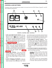
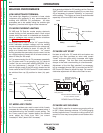
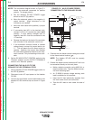
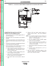

NOTE: The connection diagram shown in Figure C.1
shows the electrode connected for positive
polarity. To change polarity:
a. Set the Idealarc DC-655 POWER toggle
switch to the OFF (0) position.
b. Move the electrode cable to the negative (-)
output terminal. (High inductance or low
inductance, as needed).
c. Move the work cable to the positive (+) output
terminal.
d. If connecting lead #21 to the terminal strip,
connect it to the +21 terminal (to match work
polarity). If work polarity changes back to
negative, lead #21 must be connected to the
-21 terminal.
e. Reverse the leads on the back of the ammeter
and voltmeter in the automatic control box.
f. If the automatic controls include a variable
voltage board, connect its jumper lead to pin
“L”. This will permit the inch down button to
operate. However, the jumper also disables
the cold starting/autostop feature of the auto-
matic controls. Only hot starting will be avail-
able.
6. Set the DC-655 OUTPUT CONTROL switch to the
“Remote” position and the OUTPUT TERMINALS
switch in the “Remote” position.
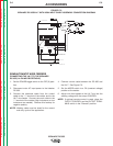
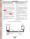
CONNECTING THE NA-5/-5R TO THE
IDEALARC DC-655 (TERMINAL STRIP)
1. Set the Idealarc DC-655 POWER toggle switch to
the OFF (0) position.
2. Disconnect main AC input power to the Idealarc
DC-655.
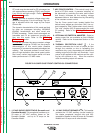
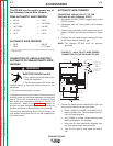
3. Connect the wire feeder control cable leads to the
Idealarc DC-655 terminal strip as shown in Figure
C.2.
FIGURE C.2 – NA-5/-5R WIRE FEEDER
CONNECTION TO THE IDEALARC DC-655
4. Connect the wire feeder control cable ground lead
to the frame terminal marked .
NOTE: The Idealarc DC-655 must be properly
grounded.
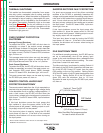
5. Extend wire feeder control cable lead #21 so it can
be connected directly to the work piece.
a. Make a bolted connection using AWG #14 or
larger insulated wire. Tape the bolted connec-
tion with insulating tape.
b. An S-16586-X remote voltage sensing work
lead is available for this purpose.
c. Keep the #21 lead electrically separate from
the work cable circuit and connection.
d. Tape the #21 lead to work cable for ease of
use.
ACCESSORIES
C-4 C-4
IDEALARC DC-655
Return to Section TOC Return to Section TOC Return to Section TOC Return to Section TOC
Return to Master TOC Return to Master TOC Return to Master TOC Return to Master TOC
NEGATIVE
POSITIVE
32
31
2
4
GND
21
TO WORK
POWER SOURCE
21
FOR CONTROL CABLE
WITH 14 PIN MS-TYPE
PLUG CONNECTOR
OR
FOR CONTROL CABLE
WITH TERMINAL STRIP
LEAD CONNECTORS
CONTROL CABLE
14-PIN
RECEPTACLE
A
B
C
INPUT CABLE PLUG
CONTROL CABLE
41
4 2 31
32
75 76
77
21
-
21
+
REMOTE VOLTAGE SENSING LEAD
TO NA-5/-5R
BOLT TO CABLES FROM NA-5/-5R
WIRE CONTACT AS'BLY