


Return to Section TOC Return to Section TOC Return to Section TOC Return to Section TOC
Return to Master TOC Return to Master TOC Return to Master TOC Return to Master TOC
TROUBLESHOOTING & REPAIR
F-25 F-25
IDEALARC DC-655
MAIN TRANSFORMER (T1) VOLTAGE TEST (continued)
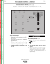
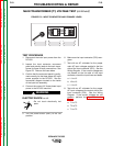
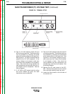
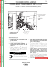
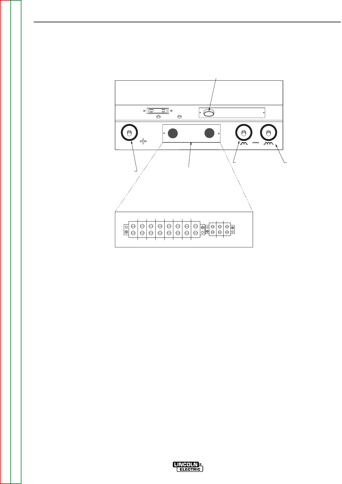
10. Test for 115 VAC between leads #31 and
#32 on the terminal strip. The terminal strip
can be accessed by removing the small
panel at the lower portion of the case front.
See Figure F.8. 115 VAC AC should also be
present at the 115 VAC receptacle. If the
correct voltage is not present, make sure
the 20 amp circuit breaker is not tripped or
faulty. Also check the wiring between the
main transformer, the terminal strip, the cir-
cuit breaker and the receptacle. See the
Wiring Diagram.
11. If 115 VAC is NOT present and the wiring
and circuit breaker are good, the main
transformer may be defective.
12. Test for 42 VAC between leads #41 and #2
on the terminal strip. The terminal strip can
be accessed by removing the small panel
at the lower portion of the case front. See
Figure F.8. If the correct voltage is not pre-
sent, make sure the 10 amp circuit breaker
is not tripped or faulty. Also check the
wiring between the main transformer, the
terminal strip, and the circuit breaker. See
the Wiring Diagram.
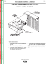
13. Remove the AC input power to the DC-
655. Remove the screws from the control
box cover and carefully lower the cover.
14. Locate the firing board on the left side of
the control box.
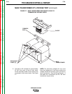
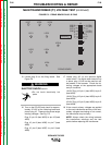
FIGURE F.8 - TERMINAL STRIP
POSITIVE
OUTPUT
TERMINAL
LOW INDUCTANCE
NEGATIVE OUTPUT
TERMINAL
HIGH INDUCTANCE
NEGATIVE OUTPUT
TERMINAL
TERMINAL STRIP
COVER PANEL
14 PIN MS RECEPTACLE
+21
-21 41 4 2 31 32 75 76
77
TERMINAL STRIP