


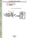
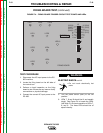
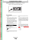
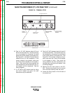

12. Test for 9.5 VDC to 11.0 VDC between
leads #231 and #215 on the firing board.
Make sure the Mode Switch (SW2) is in a
constant voltage (CV) position.
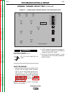
Locate plug J5 on the firing board. Locate
leads #231 (pin-13) and #215 (pin-12). See
Figure F.4.
Connect a jumper wire from pin C (lead #2)
to pin D (lead #4) at the 14-pin receptacle.
(Or put the Output Terminal Switch in the
ON position.) This should initiate machine
output at the welding terminals.
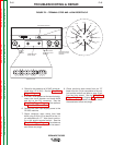
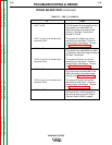
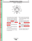
Rotate the Output Control (R1) clockwise
and counter-clockwise. The DC voltage
between leads #231 and #215 should vary
from 9.5 VDC to 11.0 VDC as the control is
turned from minimum to maximum. If the
voltage varies and LEDs 1 through 6 do
NOT vary in brightness, the firing board
may be faulty.
If the voltage does NOT vary, the control
board, control potentiometer or associated
leads may be faulty. See the Wiring
Diagram.
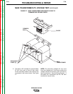
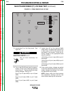
13. Test for approximately 5.5 VDC between
leads #231 and #215 on the firing board.
See Figure F.4.
Put the Mode Switch (SW2) in the constant
current (CC) position.
Rotate the Output Control (R1) clockwise
and counter-clockwise. The DC voltage
between leads #231 and #215 should be
constant at approximately 5.5 VDC. This
voltage should not vary when the output
control is turned.
TROUBLESHOOTING & REPAIR
F-21 F-21
IDEALARC DC-655
Return to Section TOC Return to Section TOC Return to Section TOC Return to Section TOC
Return to Master TOC Return to Master TOC Return to Master TOC Return to Master TOC