


TROUBLESHOOTING & REPAIR
F-41 F-41
IDEALARC DC-655
Return to Section TOC Return to Section TOC Return to Section TOC Return to Section TOC
Return to Master TOC Return to Master TOC Return to Master TOC Return to Master TOC
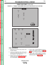
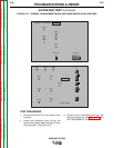
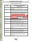
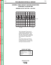
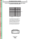
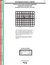
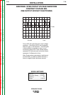
THERMAL FAN/SNUBBER BOARD LED CHART
LED # LED FUNCTIONS AND INDICATIONS
(Machine is ON)
1 Indicates fan should be running.
2Indicates welding current is greater than 200 amps.
3 Indicates fan should be running due to heating of main
SCRs.
4 Indicates an open thermal fan thermistor or an open con-
nection between the thermistor and the thermal fan/snub-
ber board. See the Wiring Diagram (leads #319 and
#316).
5 Indicates a thermostat (choke or secondary) has opened.
The thermal protection light should also be illuminated.
6 Indicates the fan motor should be running. LED 6 should
be illuminated and the fan running when any
of the following LEDs are lit: LED 2, LED 3, LED 4, or
LED 5.