


Return to Section TOC Return to Section TOC Return to Section TOC Return to Section TOC
Return to Master TOC Return to Master TOC Return to Master TOC Return to Master TOC
TROUBLESHOOTING & REPAIR
F-53 F-53
IDEALARC DC-655
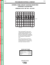
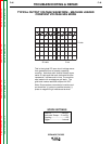
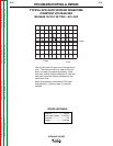
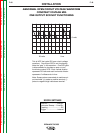
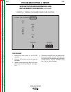
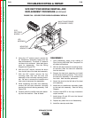
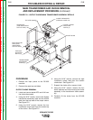
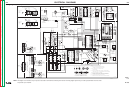
FIGURE F.20 – SCR RECTIFIER BRIDGE ASSEMBLY DETAILS
SCR
RECTIFIER
BRIDGE
LEG
ASSEMBLY
MOUNTING
BRACKETS
MAIN TRANSFORMER
SECONDARY LEADS
SCR RECTIFIER BRIDGE REMOVAL AND
REPLACEMENT PROCEDURE (continued)
5. Using the 1/2” socket wrench, remove the
six transformer secondary leads from the
heat sink assembly. The small “A” leads do
not have to be removed. Note lead place-
ment for reassembly. See the Wiring
Diagram and Figure F.20.
6. With the 9/16” wrench, remove the shunt
from the left side of the heat sink assembly.
7. With the 3/8” wrench, remove the four
mounting bolts that hold the heat sink
assembly to the horizontal mounting brack-
ets. Be sure to remove the insulators and
take note of placement for reassembly.
8. While supporting the heat sink assembly,
remove the left side horizontal mounting
bracket from the left side leg assembly. See
Figure F.20.
9. Carefully slide the rectifier heat sink assem-
bly from the machine. Clear all leads.
REASSEMBLY
1. Upon reassembly, apply a thin coating of
Dow Corning 340 Heat Sink Compound to
all bolted connections.
2. With the left side horizontal mounting brack-
et removed, slide the heat sink assembly
into the machine.
3. Support the heat sink assembly and install
the left side mounting bracket. Then mount
the heat sink assembly to the bracket with
four bolts. Note insulator placement.
4. Attach the shunt to the left side of the heat
sink assembly.
5. Install the six transformer secondary leads
to the heat sink assembly. See the Wiring
Diagram.
6. Connect lead #222 to the high inductance
output terminal.
7. Install plugs J9 and J20 onto the thermal
fan/snubber board.
8. Replace any cable ties cut at disassembly.
9. Install the case top and sides.