


Return to Section TOC Return to Section TOC Return to Section TOC Return to Section TOC
Return to Master TOC Return to Master TOC Return to Master TOC Return to Master TOC
TROUBLESHOOTING & REPAIR
F-18 F-18
IDEALARC DC-655
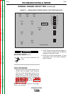
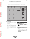
FIRING BOARD TEST (continued)
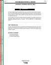
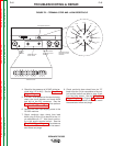
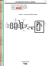
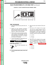
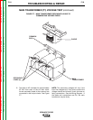
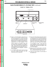
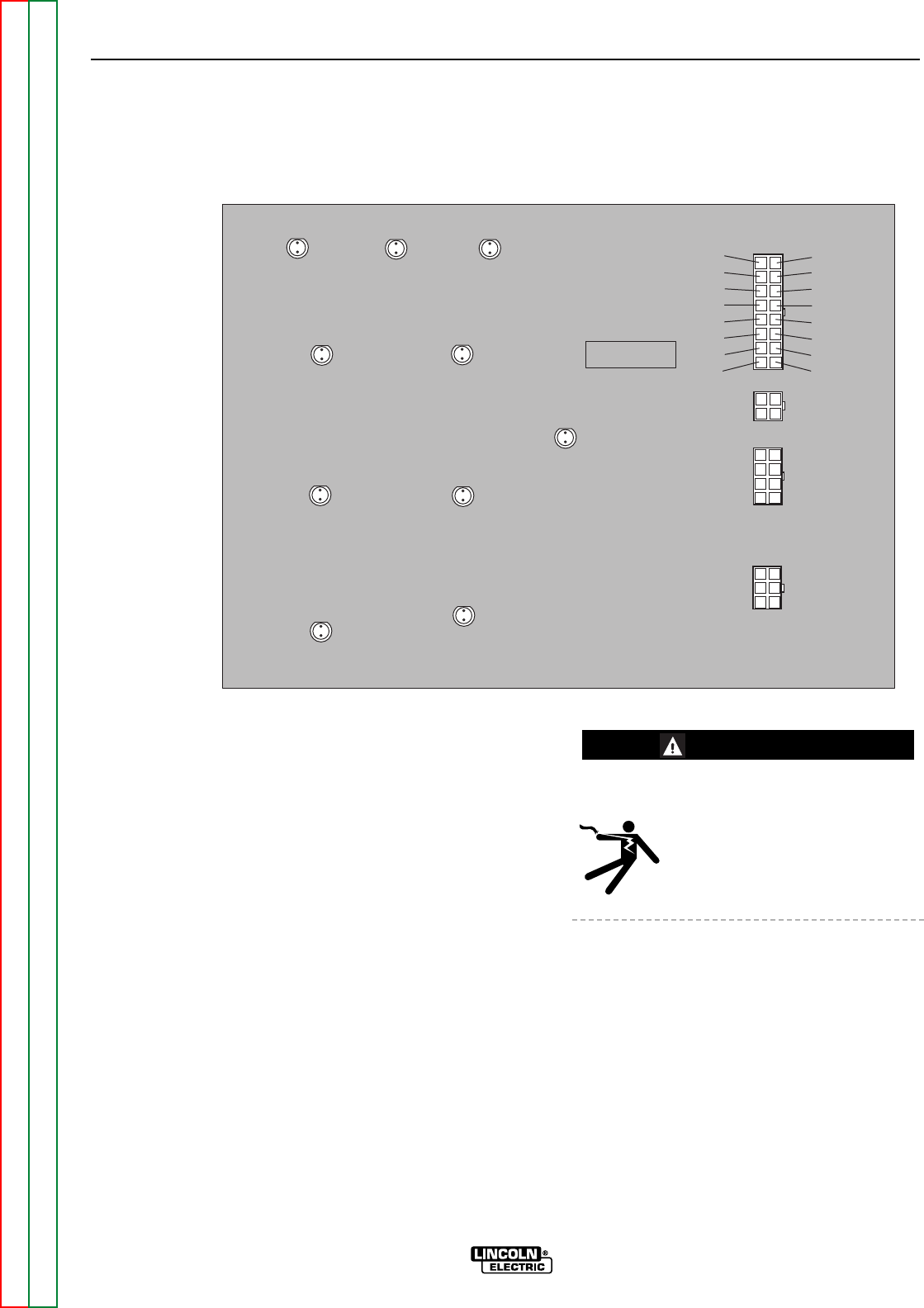
FIGURE F.4 – FIRING BOARD TRIGGER CIRCUIT TEST POINTS AND LEDs
FIRING BOARD
G2699-[ ]
16 (204)
15 (203)
14
13 (231)
12 (215)
11
10
9
(205) 8
(206) 7
(207) 6
(208) 5
4
3
2
1
LED7 LED8 LED9
LED1
LED2
LED3
LED4
LED5
LED6
LED10
J5
J6
J7
J4
TEST PROCEDURE
1. Disconnect the AC input power to the DC-
655 machine.
2. Locate the firing board on the left side of
the control box.
3. Perform a visual inspection on the firing
board to see if there are any loose or faulty
connections or physical damage.
4. Connect the correct AC input power to the
DC-655.
ELECTRIC SHOCK can kill.
• Do not touch electrically hot
parts.
5. Turn the power switch (SW1) to the ON
position.
6. LEDs 7, 8 and 9 should be lit and equally
bright. See Figure F.4 to locate the LEDs.
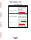
Use Table F.1 to check operation of LEDs 7,
8, and 9. The three LEDs should be of
equal intensity.
WARNING