


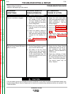
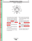
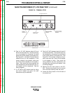

7. Connect a jumper wire from pin C (lead #2)
to pin D (lead #4) at the 14-pin receptacle.
See Figure F.5. (Or put the Output Terminal
Switch in the ON position.) This should ini-
tiate machine output at the welding termi-
nals. LED 10 on the firing board should
now be on. See Table F.1. If LED 10 does
not glow when leads #2 and #4 are con-
nected together, perform the Internal
Trigger Test. The firing board may be
faulty.
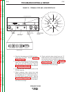
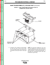
8. Locate LEDs 1 to 6 on the firing board. See
Figure F.4. Each LED should glow with
equal brightness.
NOTE: LEDs 1 through 6 indicate that the
SCR gate firing signals are being generated
by the firing board.
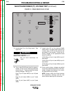
9. Set the Output Control Switch (SW3) in the
“Output Control at DC-655” (local) position.
10. Set the Mode Switch (SW2) in a constant
voltage (CV) position.
11. Rotate the Output Control Potentiometer
(R1). As the pot is turned clockwise, LEDs
1 through 6 should get brighter. As the pot
is turned counter-clockwise, the LEDs
should get dimmer.
If the LEDs glow and change in brightness
equally as the pot is turned, and the prob-
lem continues, the SCR bridge may be
faulty. Perform the SCR Output Bridge
Test.
If one or two lights stay bright or dim and
the others change, this could indicate an
open or shorted gate lead or faulty snubber
board. Perform the SCR Output Bridge
Test. If the Output Bridge and associated
gate leads are OK, the firing board may be
faulty.
If all of LEDs 1 through 6 do not glow or do
not change in brightness equally as the
output control is rotated, go to step 12.
TROUBLESHOOTING & REPAIR
F-20 F-20
IDEALARC DC-655
Return to Section TOC Return to Section TOC Return to Section TOC Return to Section TOC
Return to Master TOC Return to Master TOC Return to Master TOC Return to Master TOC
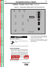
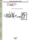
FIGURE F.5 – 14-PIN RECEPTACLE
J=31
I=41
N
H=21
G=75
M
E=77
D=4
C=2
L
B=GND
A=32
K=42
F=76