


Return to Section TOC Return to Section TOC Return to Section TOC Return to Section TOC
Return to Master TOC Return to Master TOC Return to Master TOC Return to Master TOC
TROUBLESHOOTING & REPAIR
F-39 F-39
IDEALARC DC-655
ACTIVE SCR TEST (continued)
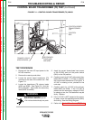
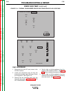
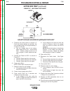
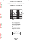
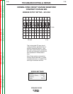
FIGURE F.16 – THERMAL FAN/SNUBBER BOARD AND FIRING BOARD PLUG LOCATIONS
THERMAL FAN / SNUBBER
LED5
LED1
LED2
LED3
LED4
LED6
PLUG J9
L10124-[ ]
FIRING BOARD
G2699-[ ]
LED7 LED8 LED9
LED1
LED2
LED3
LED4
LED5
LED6
LED10
J5
J6
J7
J4
PLUG J20
TEST PROCEDURE
1. Disconnect the main AC input power to the
machine.
2. Locate and disconnect plug J9 from the
thermal fan/snubber board and plug J5 from
the firing board. See Figure F.16.
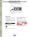
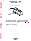
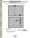
3. Remove the red insulating paint from the
heat sink test points. See Figure F.17. DO
NOT DISASSEMBLE THE HEAT SINKS.