


CONNECTING THE LN-8 OR LN-9 TO THE
IDEALARC DC-655 (14-PIN MS RECEPTACLE)
1. Set the POWER toggle switch to the OFF (0) posi-
tion.
2. Disconnect main AC input power to the Idealarc
DC-655.
3. Connect the electrode cable from the LN-8 or
LN-9 to the “+” terminal of the welder. Connect
the work cable to the “-” terminal of the welder
(High inductance or low inductance as needed).
Reverse this hookup for negative polarity. See
Figure C.4.
NOTE: Welding cable must be sized for the current
and duty cycle of the application.
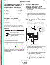
4. Connect the control cable between the 14-pin MS
receptacle on the DC-655 and the input cable plug
on the LN-8 or LN-9. See Figure C.4.
5. Set the MODE switch to a CV (constant voltage)
position.
6. Adjust wire feed speed at the LN-8 or LN-9 and
set the welding voltage with the WIRE FEEDER
VOLTAGE CONTROL.
Place the OUTPUT CONTROL switch in the “Remote”
position and the OUTPUT TERMINALS switch in the
“Remote” position.
CONNECTING THE DH-10 TO THE
IDEALARC DC-655 (14-PIN MS RECEPTACLE)
1. Set the POWER toggle switch to the OFF (0) posi-
tion.
2. Disconnect main AC input power to the Idealarc
DC-655.
3. Connect the electrode cable from the DH-10 to the
“+” terminal of the welder. Connect the work
cable to the “-” terminal of the welder (High induc-
tance or low inductance as needed). Reverse this
hookup for negative polarity.
NOTE: Welding cable must be sized for the current
and duty cycle of the application.
4. Connect the DH-10 input cable between the 14-
pin MS receptacle on the DC-655 and the input
cable plug on the DH-10. See Figure C.5.
5. Set the MODE switch to a CV (constant voltage)
position.
6. Adjust wire feed speed at the DH-10 and set the
welding voltage with the WIRE FEEDER VOLTAGE
CONTROL.
7. Set the DIP switches on the DH-10 for DC-655.
See the DH-10 Operator’s Manual.
Place the OUTPUT CONTROL switch in the “Remote”
position and the OUTPUT TERMINALS switch in the
“Remote” position.
ACCESSORIES
C-9 C-9
IDEALARC DC-655
Return to Section TOC Return to Section TOC Return to Section TOC Return to Section TOC
Return to Master TOC Return to Master TOC Return to Master TOC Return to Master TOC
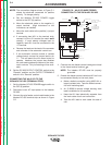
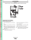
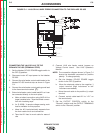
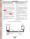
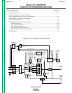
FIGURE C.5 – IDEALARC DC-655 DH-10 CONNECTION
ELECTRODE CABLE
-
+
14 PIN
AMPHENOL
POWER SOURCE
TO WORK
DH-10
WIRE
FEEDER
LINCOLN CV-655
DH-10
INPUT CABLE
ASSEMBLY
9 PIN
AMPHENOL
N.E.