


Return to Section TOC Return to Section TOC Return to Section TOC Return to Section TOC
Return to Master TOC Return to Master TOC Return to Master TOC Return to Master TOC
TROUBLESHOOTING & REPAIR
F-50 F-50
IDEALARC DC-655
CLEANING PROCEDURE
1. Remove the main input supply power to the
machine.
2. Locate and get access to the input contac-
tor (CR1) in the input box. See Figure F.18.
3. Remove the input contactor cover plate
using a phillips head screwdriver.
Do not apply input power to
the machine with the input
contactor cover plate re-
moved.
4. Blow out any dirt or dust in or around the
contacts with a low pressure air stream.
5. Inspect the contacts for signs of excessive
wear, pitting, or contacts fused (stuck)
together.
a. If any of these conditions are present,
replace the input contactor assembly.
6. Replace the input contactor cover plate.
CONTACTOR REPLACEMENT
PROCEDURE
1. Disconnect main input supply power to the
machine.
2. Locate and get access to the input contac-
tor (CR1) in the input box. See Figure F.18.
3. Disconnect the main input supply power
leads L1, L2, and L3 to the input contactor.
Remove the control transformer primary
leads H1, H2 or H3 (dependent on input volt-
age) from the L1 and L3 terminals on the
input side of the contactor.
4. Disconnect the output leads T1, T2, and T3
from the input contactor.
5. Identify and label the leads connected to the
input contactor coil. See the Wiring
Diagram.
6. Disconnect the leads from the input contac-
tor coil (leads X1, #256 and #255A). See the
Wiring Diagram.
7. Remove the three self-tapping mounting
screws using a 5/16” socket wrench.
8. Remove the input contactor.
9. Insert the replacement input contactor and
install it following the procedures in reverse
order.
NOTE: Be sure to reconnect all leads cor-
rectly.
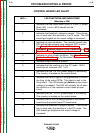
INPUT CONTACTOR (CR1) CLEANING/REPLACEMENT (continued)
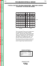
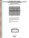
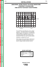
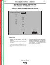
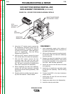
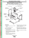
FIGURE F.18 - INPUT CONTACTOR CLEANING AND REMOVAL
1. INPUT SUPPLY LINE
2. INPUT CONTACTOR CR1
3. RECONNECT PANEL
WARNING