


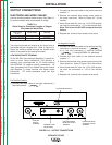
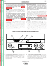
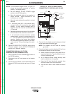

3. 42 VAC 10 AMP CIRCUIT BREAKER - This
breaker protects the 42 VAC auxiliary circuits locat-
ed in the terminal strip and MS-receptacle.
4. 14-PIN MS-RECEPTACLE - This connector pro-
vides easy connection for a wire feeder control
cable. It provides connections for auxiliary power,
output switching, remote output control, wire feed-
er voltmeter sense lead and ground. Refer to 14-
Pin MS Type Receptacle in the Installation
Section of this manual for information about the cir-
cuits made available at this receptacle.
5. TERMINAL STRIP COVER PANEL - Remove this
panel to gain access to the circuits made available
at the terminal strip and the 4-pin receptacle for the
optional paralleling kit. This terminal strip contains
the same circuits as the 14-pin MS-receptacle.
The cover also provides for installation of cable
strain relief clamps.
6. POSITIVE OUTPUT TERMINAL - This output ter-
minal is for connecting a welding cable. To change
welding polarity and for proper welding cable size
refer to Electrode and Work Cables in the
Installation Section of this manual.
7. NEGATIVE OUTPUT TERMINALS - These output
terminals are for connecting a welding cable to
either the High Inductance or Low Inductance
Terminal for desired arc characteristics. To change
welding polarity and for proper welding cable size
refer to Electrode and Work Cables in the
Installation Section of this manual.
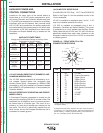
CASE BACK CONNECTIONS
220 VAC AUXILIARY RECEPTACLE
(European and Export Models)
This receptacle provides up to 2 amps of 220 VAC
auxiliary power for a water cooler.
220 VAC 2 AMP CIRCUIT BREAKER
(European and Export Models)
This breaker protects the 220 VAC auxiliary circuit
located in the 220 VAC receptacle.
AUXILIARY POWER
42 volt AC auxiliary power, as required for some wire
feeders, is available through the wire feeder recepta-
cle. A 10 amp circuit breaker protects the 42 volt cir-
cuit from overloads.
DC-655 machines can also supply 115 volt AC auxil-
iary power through the wire feeder receptacle. A 20
amp circuit breaker on the Domestic model, and a 15
amp on the Canadian and Export models protects the
115 volt circuit from overloads. 115 VAC is not avail-
able in the MS-receptacle on the European models.
Note that some types of equipment, especially pumps
and large motors, have starting currents which are sig-
nificantly higher than their running current. These high-
er starting currents may cause the circuit breaker to
open. If this situation occurs, the user should refrain
from using the DC-655 auxiliary power for that equip-
ment.
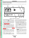
MACHINE PROTECTION
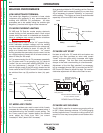
THERMAL FAN CONTROL
The machine’s cooling fan remains off when the tem-
perature of the rectifiers and windings inside the
machine are below that requiring air flow cooling, as
determined by electronic monitoring of several thermal
sensors and the welding current of the machine.
Depending upon the operating temperature of the
machine, the fan may remain off while welding but
once the fan is activated, it will remain on for at least 5
minutes to assure proper cooling. This feature saves
energy and also minimizes the amount of dirt and
other air borne particles being drawn into the machine.
FAN MOTOR FUSE
(European Model)
A 10 amp slow blow fuse protects the fan motor cir-
cuit. This fuse is located inside the DC-655 mounted
on the fan motor bracket.
MACHINE SHUTDOWN
The DC-655 provides shutdown modes for thermal
over-heating, excessive load currents and faults. It
also provides an idle timer shutdown feature for addi-
tional operating economy.
OPERATION
B-6 B-6
IDEALARC DC-655
Return to Section TOC Return to Section TOC Return to Section TOC Return to Section TOC
Return to Master TOC Return to Master TOC Return to Master TOC Return to Master TOC
CAUTION