


Return to Section TOC Return to Section TOC Return to Section TOC Return to Section TOC
Return to Master TOC Return to Master TOC Return to Master TOC Return to Master TOC
TROUBLESHOOTING & REPAIR
F-13 F-13
IDEALARC DC-655
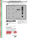
INTERNAL TRIGGER CIRCUIT TEST
WARNING
Service and repair should be performed by only Lincoln Electric factory trained person-
nel. Unauthorized repairs performed on this equipment may result in danger to the tech-
nician or machine operator and will invalidate your factory warranty. For your safety and
to avoid electrical shock, please observe all safety notes and precautions detailed
throughout this manual.
If for any reason you do not understand the test procedures or are unable to perform the
test/repairs safely, contact the Lincoln Electric Service Department for electrical trou-
bleshooting assistance before you proceed. Call 216-383-2531 or 1-800-833-9353
(WELD).
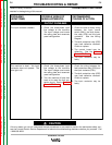
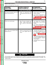
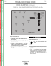
TEST DESCRIPTION
This test will help determine if the wiring and connections are good from the 14-pin
receptacle and terminal strip through the P15 and P16 connectors and thermostats to the
firing board. The technician will also be able to determine if the 42 VAC trigger supply
voltage is present.
MATERIALS NEEDED
Ohmmeter (Multimeter)
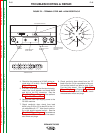
DC-655 Wiring Diagram
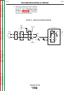
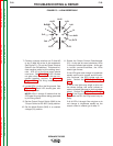
Simplified Trigger Diagram