


TROUBLESHOOTING & REPAIR
F-29 F-29
IDEALARC DC-655
Return to Section TOC Return to Section TOC Return to Section TOC Return to Section TOC
Return to Master TOC Return to Master TOC Return to Master TOC Return to Master TOC
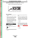
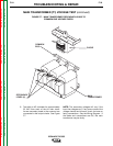
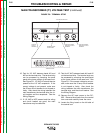
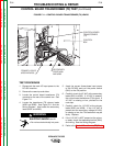
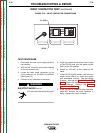
5. Locate the control transformer secondary
leads. See Figure F.10. Lead X1 is con-
nected to the coil terminal on the CR1 input
contactor. Lead X2 is spliced into lead
#211, which is then connected to the input
power switch (SW1).
HIGH VOLTAGE is present at
the input leads.
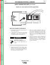
6. Apply the correct three-phase input power
to the DC-655 and check for 115 VAC at
leads X1 to X2.
NOTE: The DC-655 does not have to be ON
to perform this test. If the main AC input
supply voltage varies, the control trans-
former secondary voltage will vary by the
same percentage.
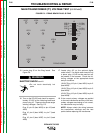
7. If approximately 115 VAC is present at leads
X1 to X2, the control transformer is function-
ing properly.
8. If approximately 115 VAC is NOT present at
leads X1 to X2, make certain the correct
input voltage is being applied to the primary
winding of the control transformer and that
the correct primary leads (H1, H2, H3, etc.)
are being used. See the connection infor-
mation diagram on the input access door.
9. If the correct voltage is being applied to the
primary of the control transformer and the
secondary voltage is incorrect or not pre-
sent, the control transformer may be defec-
tive.
CONTROL TRANSFORMER (T2) TEST (continued)
WARNING