


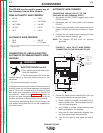

THERMAL SHUTDOWN
This welder has thermostatic protection from exces-
sive duty cycles, overloads, loss of cooling, and high
ambient temperature. When the welder is subjected to
an overload or loss of cooling, a thermostat will open.
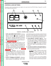
This condition will be indicated by the illumination of
the yellow Thermostatic Protection Light on the case
front (see Figure B.1). The fan will continue to run to
cool the power source. No welding is possible until the
machine is allowed to cool and the Thermostatic
Protection Light goes out.
OVER CURRENT PROTECTION
SHUTDOWN
Average Current Shutdown
To protect the SCR’s , the DC-655 will shut down to
essentially no output if the output current averages
over 900 amps for about 5-6 seconds, and in less than
0.3 seconds if averaging over 1200 amps (shorter time
for higher current). Control PC board LED4, shutdown
light, will turn on.
This average current shut down can only be reset by
opening the feeder gun trigger, or switching the DC-
655 Output/Remote switch out of the “on” position.
Peak Current Shutdown
To protect the SCRs, the DC-655 will shut down imme-
diately to essentially no output if the peak output cur-
rent exceeds 2500 amps (about 1800A average).
Control PC board LED4, shutdown light, will turn on.
This peak current shut down can be reset by turning
the DC-655 input power off, then on.
REMOTE CONTROL LEADS FAULT
PROTECTION SHUTDOWN
1
The remote control leads from the 14-pin receptacle or
terminal strip are protected against high voltage faults
to the electrode circuit or auxiliary voltage supplies. If
such a fault occurs, the DC-655 will shut down the
input primary voltage to the transformer to prevent the
fault output. Control PC board LED3, input shutdown
light, turns on.
If this input shutdown occurs the input power pilot
light remains lit, since the power switch is ON and
control power is still present. Welding output or auxil-
iary supply output will not be present.
This input shut down is reset by turning the DC-655
input power off, then on. If the fault is not corrected
however, the shutdown will re-occur when turning on
the input power.
1
Note on earlier machines: LED4 will turn on and output will be
disabled if this fault occurs.
SHORTED RECTIFIER FAULT PROTECTION
If a short occurs across one of the silicon controlled
rectifiers of the DC-655, a potentially hazardous AC
voltage could appear across the welding output termi-
nals, even in idle mode when no output should be pre-
sent. If such a fault occurs, the DC-655 will shut down
the input primary voltage to the transformer to prevent
the fault output. Control PC board LED3, input shut-
down light, turns on.
If this input shutdown occurs the input power pilot
light remains lit, since the power switch is ON and
control power is still present. Welding output or auxil-
iary supply output will not be present.
This input shut down is reset by turning the DC-655
input power off, then on. If the fault is not corrected
however, the shutdown will re-occur when turning on
the input power.
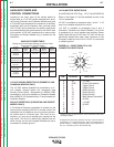
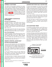
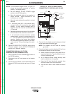
IDLE SHUTDOWN TIMER
For additional operating economy, the DC-655 can be
set up to automatically shut off the primary input
power to the main transformer after a selectable time
(1/2 or 2 hr.) has expired without welding. The unex-
pired timer is reset with each weld.
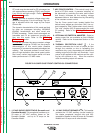
The idle mode timer is activated by setting Switch #1
(left most) of the DIP Switch located on the lower-cen-
ter of the DC-655 Control PC board. from the down
(Off) position to the up (On) position. Setting Switch
#2 of the DIP switch to up (On) sets the shutdown time
to 2 hours. Setting Switch #2 of the DIP switch to
down (Off) sets the shutdown time to 1/2 hour.
Shutdown is reset by turning the DC-655 input power
off, then on.
OPERATION
B-7 B-7
IDEALARC DC-655
Return to Section TOC Return to Section TOC Return to Section TOC Return to Section TOC
Return to Master TOC Return to Master TOC Return to Master TOC Return to Master TOC
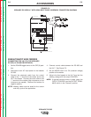
1 2 3 4
Switch #2 Time selection
(UP=2 hours, Down=1/2 hour)
Switch #1 Timer On/Off
(UP=ON, Down=OFF)
DIP Switch
See Weld Performance section
for use of switch #3 and #4.
Note: