


Return to Section TOC Return to Section TOC Return to Section TOC Return to Section TOC
Return to Master TOC Return to Master TOC Return to Master TOC Return to Master TOC
INSTALLATION
A-7 A-7
IDEALARC DC-655
AUXILIARY POWER AND
CONTROL CONNECTIONS
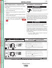
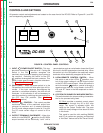
Located at the lower front of the welder behind a
hinged door is a 115 VAC duplex receptacle for auxil-
iary power (Domestic and Canadian Models only) and
a 14-pin MS type receptacle for connection of auxiliary
equipment such as wire feeders. Also, terminal strips
with 115 VAC and connections for auxiliary equipment
are located behind the access panel on the lower case
of the welder. A 220 VAC receptacle for a water cooler
(European and Export Models only) is located on the
case back.
115 VAC DUPLEX RECEPTACLE (DOMESTIC AND
CANADIAN MODELS ONLY)
The 115 VAC duplex receptacle is protected by a cir-
cuit breaker located below the receptacle (see
Auxiliary Power Table). Receptacle is a NEMA 5-20R
(protected by a 20 amp breaker) on Domestic Models
and a NEMA 5-15R (protected by a 15 amp breaker) on
Canadian Models.
230 VAC RECEPTACLE (EUROPEAN AND EXPORT
MODELS ONLY)
A Continental European receptacle is located on the
rear panel for supplying 220 VAC to a water cooler. The
receptacle has a protective cover to prevent acciden-
tal contact and is a Schuko type. The circuit is pro-
tected by a 2 amp circuit breaker also located on the
rear panel. This circuit is electrically isolated from all
other circuits, but on the European Models one line is
connected to chassis ground.
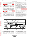
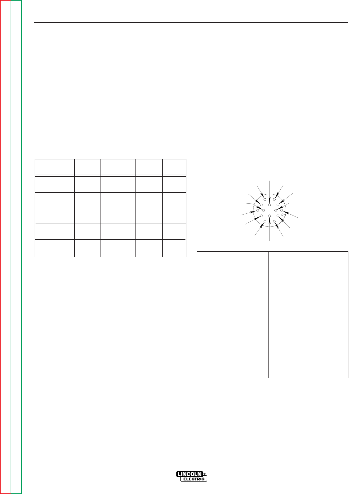
14-PIN MS TYPE RECEPTACLE
(For MS3106A-20-27PX Plug. L.E.C. Part #S12020-32)
Refer to the Figure A.4 for the available circuits in the
14-pin receptacle.
42 VAC is available at receptacle pins I and K. A 10
amp circuit breaker protects this circuit.
115 VAC is available at receptacle pins A and J
(Domestic, Canadian and Export Models). This circuit
is protected by a circuit breaker (see Auxiliary Power
Table). Note that the 42 VAC and 115 VAC circuits are
electrically isolated from each other. However, on the
European model one line of the 115 VAC is connected
to chassis ground.
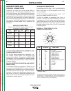
AUXILIARY POWER TABLE
Voltage and Circuit Breaker Ratings at Auxiliary Power
Connections for Various Models
Auxiliary Domestic Canadian European Export
Power Models Model Models Models
Connections (60Hz)
(230/460/575V/60 Hz)
(50/60 Hz) (50/60 Hz)
At Duplex 115V 20A 115V 15A No Duplex No Duplex
Receptacle
Terminal strip 115V 20A 115V 15A 115V 15A 115V 15A
terminals 31 & 32
MS-Receptacle 115V 20A 115V 15A
Open Circuit
115V 15A
pins A & J
MS-Receptacle 42V 10A 42V 10A 42V 10A 42V 10A
pins I & K
At 220V
No Receptacle No Receptacle 220V 2A 220V 2A
Receptacle
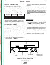
FIGURE A.4 - FRONT VIEW OF 14-PIN
CONNECTOR RECEPTACLE
PIN LEAD NO. FUNCTION
A 32 115 VAC
B GND Chassis Connection
C 2 Trigger Circuit
D 4 Trigger Circuit
E 77 Output Control
F 76 Output Control
G 75 Output Control
H 21 Work Sense Connection
2
I 41 42 VAC
J 31 115 VAC
1.
K 42 42 VAC
L --- ---
M --- ---
N --- ---
F=76
G=75
H=21
I=41
J=31
K=42
A=32
B=GND
C=2
D=4
E=77
L N
M
1.
115VAC circuit is not present in the 14-pin connector on IEC 974-
1 European models.
2.
As shipped from the factory Lead #21 from the 14-pin connector is
connected to “-21”on the terminal strip. This is the configuration for
positive welding. If welding negative polarity, connect lead #21 to
the “+21” connection point on the terminal strip.