


Receiving & Installation 3-3MN1854
System Grounding
Continued
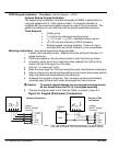
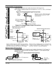
Ungrounded Distribution System
With an ungrounded power distribution system it is possible to have a continuous
current path to ground through the MOV devices. To avoid equipment damage, an
isolation transformer with a grounded secondary is recommended.
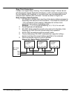
Input Power Conditioning
Certain power line conditions must be avoided. An AC line reactor or an isolation
transformer may be required for some power conditions.
• If the feeder or branch circuit that provides power to the driver has
permanently connected power factor correction capacitors, an input AC
line reactor or an isolation transformer must be connected between the
power factor correction capacitors and the driver.
• If the feeder or branch circuit that provides power to the driver has power
factor correction capacitors that are switched on line and off line, the
capacitors must not be switched while the driver is connected to the AC
power line. If the capacitors are switched on line while the driver is still
connected to the AC power line, additional protection is required. TVSS
(Transient Voltage Surge Suppressor) of the proper rating must be
installed between the AC line reactor or an isolation transformer and the
AC input to the driver.
Power Disconnect A power disconnect should be installed between the input power service
and the driver for a fail–safe method to disconnect power. The driver will remain in
a powered-up condition until all input power is removed from the driver and the
internal bus voltage is depleted.
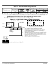
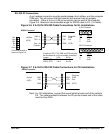
Protection Devices The driver must have a suitable input power protection device installed.
Input and output wire size is based on the use of copper conductor wire rated at
75 °C. Table 3-1 describes the wire size to be used for power connections and the
ratings of the protection devices. Use the recommended circuit breaker or fuse
types as follows:
Circuit Breaker: 1 phase, thermal magnetic.
Equal to GE type THQ or TEB for 115 VAC
Time Delay Fuses: Buss LPN on 115 VAC or equivalent.
Recommended fuse sizes are based on the following:
UL 508C suggests a fuse size of four times the continuous output
current of the driver.
Dual element, time delay fuses should be used to avoid nuisance trips
due to inrush current when power is first applied.