


3-10 Receiving & Installation MN1854
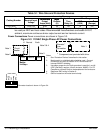
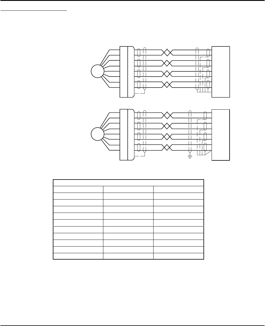
Encoder Connections (Refer to MN1800 for wire color and lead information.)
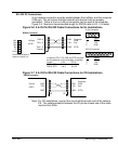
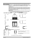
The location for each encoder connector (Side Panel) is shown in Figure 3-4.
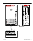
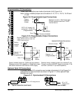
Twisted pair shielded wire with an overall shield should be used. Figures 3-12 and
3-13 show the connections between the encoder and the encoder connector.
Figure 3-12 Differential Encoder Connections for UL Installations
A+
A–
B+
B–
+5V
Com
Encoder
C+ (Index)
C– (Index)
Shell (Chassis)
A+
A–
B+
B–
+5V
Com
Z+
Z–
Drain
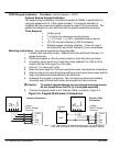
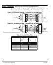
Figure 3-13 Differential Encoder Connections for CE Installations
Encoder
PE
Connection of shields to digital ground is optional.
A+
A–
B+
B–
+5V
Com
C+ (Index)
C– (Index)
Shell (Chassis)
A+
A–
B+
B–
+5V
Com
Z+
Z–
Drain
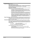
Table 3-2 Encoder Color Code
Encoder
Signal PVS100 Danaher (9–Pin D)
A+ White Green 6
A– Gray Yellow 1
B+ Orange Blue 8
B– Red Violet 3
Z+ (Index) N/A Red 9
Z– (Index) N/A Orange 5
+5VDC Black Brown 7
GND Brown Black 2
Inner shield Blue – 4
Outer shield Violet – Shell