


5-8 Setup MN1854
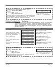
Table 5-1 Continued
Char Keypad Display Input Character Description
E
e
Extend Jog 1
Extend Jog 2
Extend Jog – When activated, the motor will Jog in the Extend (+) direction.
When the input is released, motion stops at the Jog Accel rate. If an End of
Travel limit is hit while jogging, the motor will stop at the Stop Rate (see
Edit–Setup–Misc.). Before the motor can be removed from the limit, a Stop or
Kill input must be activated to clear the fault generated by the End of Limit
switch. Serial commands S or K will also clear the fault.
The velocity is determined by the Jog Speed Input and the Jog Low and High
setup parameters. When the input is off, the speed is low. If no input is
configured for Jog Speed, the motor will jog at the Jog Low setting.
G Registration Registration – Input #1 must be configured as a Registration input for axis #1
and Input #2 must be configured as a Registration input for axis #2 – no other
inputs will work. See the RG command for more details.
I Interrupt (Run98) Interrupt (Run 98) – When activated, motion on all axes stop at the stop–rate
(see Edit–Setup–Misc–Stop–Rate). The current program is stopped, and
processing continues with the first command in program 98. If no program is
running when the input is activated, program 98 will run. This input is ignored
while the keypad is in Edit mode. This is a positive edge triggered input,
rather than a level sensitive input. If multiple inputs are configured as
Interrupts, only the first edge of the first activated input will be seen. If
subsequent Interrupt inputs go active while the first Interrupt input is active,
no additional interrupts will be seen.
Advanced Interrupt handling can be achieved using the INT98CTRL and
ARM INT98 variables. The INT98CTRL variable determines whether
Interrupts can be disabled or not. The ARM INT98 variable allows you to arm
and disarm the Interrupt as desired.
After power–up, INT98CTRL is initialized to 0. In this mode, every interrupt
results in an immediate jump to program 98, even if you just entered program
98. The value of (ARM INT98) is ignored.
When INT98CTRL=1, Interrupts can be disabled with the ARM INT98
variable. INT98CTRL=1 also initializes ARM INT98 to 1. This means the
control is watching for interrupts. When INT98CTRL is set to 1 an interrupt
causes the program to jump to program 98 and sets ARM INT98=0, disabling
any further interrupts until you re–enable them by setting ARM INT98=1. This
allows you to control when you want to re–enable Interrupts in your interrupt
service routine (program 98).
To summarize, when (INT98CTRL)=1:
If (ARM INT98)=0, Interrupts are ignored. (ARM INT98) is internally set to 0
on the first edge if the previous (ARM INT98) value was 1.
Interrupt processing will be suspended until (ARM INT98) is
reset to 1. This allows for input debounce and controlling
the ability of program 98 to interrupt itself.
If (ARM INT98)=1, The system is awaiting the first INT98 input assert edge.
Once the interrupt is seen the control will go to program 98.
Subsequent interrupts are ignored until (ARM INT98) is set
to 1.
INT98CTRL and ARM INT98 are reset to factory values on power–up.
Note: There is a space in ARM INT98.
When activated, any executing program or functional operation is terminated
and program I98 (interrupt program) is immediately executed. If a move is
executing when the interrupt is activated, the move is terminated (decelerated
at a rate determined by the Stop Deceleration rate setup parameter). The unit
will go into Run mode once program I98 is completed.