


Section 7
Troubleshooting
Troubleshooting 7-1MN1854
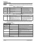
Overview The system troubleshooting procedures involve observing the status of the LED’s.
The tables in this section provide information related to the indications provided by
these devices.
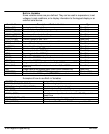
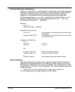
Table 7-1 Operation Indicators
LED Color Status Comments
Power Green Indicates that AC power is applied and the
supplies are operating.
LED’s will flash during power up tests but only
the Power LED should remain on.
Regen Yellow On during Regen activity. Should remain off. On when Regen circuit is
active to dump excess bus energy.
OverVoltage/
INTLK
Red Regen circuit cannot handle excess energy or
Interlock circuit is open.
This fault condition is reset by cycling power.
Temperature Red On when internal heatsink temperature exceeds
158°F (70°C).
This fault condition is reset by cycling power.
Install a fan kit, reduce the load, reduce ambient
temperature, use the Standby current setting.
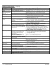
Table 7-2 Axis 1 and 2 Indicators
Stepping Green Indicates LinStep+ is sending CW (right LED) or
CCW (left LED) step pulses.
Above several steps per second the LED
becomes continuously illuminated.
Disable/Short Yellow On when the Shutdown input is activated by an
external control. The Shutdown signal also
activates the Short output, but does not turn on
the Short LED.
Short LED indicates that a Short Circuit or
Undervoltage condition has occurred. A short
circuit problem can occur because of shorted
or miswired motor leads, or internal fault.
This fault condition is reset by cycling power.
To isolate the problem, disconnect and insulate
the motor leads from the drive connector, but
leave the Interlock jumper installed. Apply
power and step pulses. If the drive does not
invoke the short circuit fault, then it is likely that
the defect is in the motor, wires or the
connections at the drive.
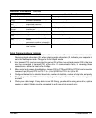
Note: The fault LED and fault Output do NOT activate the same. The fault Output indicates that
one of several fault conditions has occurred. The fault LEDs provide a means of resolving
the source of the fault.
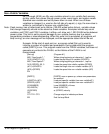
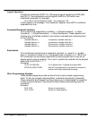
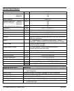
Additional Information (General)
Symptom Possible Cause Possible Remedies
The keypad is blank
with no backlight.
The keypad is not receiving +5VDC. Verify all wiring is correct.
Verify that the +5VDC is between 4.8 and 5.2V.
Display is difficult to
read
Contrast ratio is incorrectly set Adjust the contrast with the pot on the back of the keypad.
The ON LED is yellow. FLASH memory is corrupt. The operating system and user programs must be reloaded.
The ON LED is red. A Fault has occurred. The fault can be determined with the keypad or by using
serial status commands (SS, SA, SD).
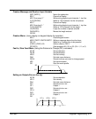
Motor moves the wrong Wrong Gear Ratio. Check distance units
distance
Motor stalled. Check motor current, inductance, anti–resonance settings
Check Speed Torque required for move, reduce
acceleration.
Motor stalls Acceleration and/or velocity too high. Reduce acceleration and/or velocity.
Motor configured incorrectly. Check motor current, inductance and anti–resonance
settings.
Motor direction is wrong The motor phases are miswired. Verify connections, or swap A+ with A–.
The system real direction is reversed. Change the control’s direction parameter.
The control does not re-
spond to keypad input.
The keypad is disabled. Check the switch settings on the back of the keypad.
The motor “whines” The inductance or anti–resonance
setting is incorrect.
Verify the Inductance setting. Operation is best with motors
4 mH or above. Otherwise, verify the anti–resonance setting.