


Section 1
General Information
3-12 Receiving & Installation MN1854
Start-Up Procedure
Power Off Checks
Before you apply power, it is very important to verify the following:
1. Verify the AC line voltage at the source matches the control rated
voltage.
2. Inspect all power connections for accuracy, workmanship and tightness.
3. Verify that all wiring conforms to applicable codes.
4. Verify that the control and motor are properly grounded to earth ground.
5. Check all signal wiring for accuracy.
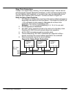
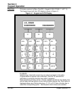
6. Set Keypad DIP switches as desired, Figure 3-15. (Power must be
cycled after a DIP switch position change).
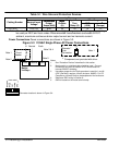
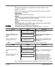
Figure 3-15 Keypad Adjustments
1234
ON
5
N/C
4213
GND Rx Tx +5VDC
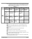
DIP Switch Keypad Operation
12
Off Off Full Keypad Operation
Off On No access to Run, ESC, Edit, Copy, Del
On Off No access to Run, Edit, Copy, Del
On On No access to Edit, Copy, Del
Switches 3 and 4 are reserved.
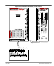
Switch and Potentiometer Settings
The motor current, inductance, and resolution settings must be made before
power is applied. The other settings (waveform, standby current, anti–resonance,
and phase offset adjustments can be made while the drive is powered and the
motor is moving.
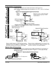
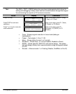
Motor Current (can be changed at any time)
Set these switches for the correct values for the motors connected to each
axis. The Motor Current range is 0.0–6.0 Amps (peak) per motor phase per axis.
Each axis has two, 10–position rotary switches (labeled Amps and Tenths of Amps
in Figure 3-4). These switches set the current for each motor. The top switch sets
the integer current value, and the bottom switch sets the tenths of amps value.
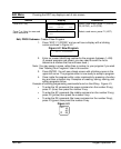
Motor Resolution (only read at power up, cycle power if changed)
Eight selectable motor resolutions (200, 400, 1,000, 5,000, 10,000, 18,000, 25,000
and 25,400 steps) are available. Rotary switches (“Res” shown in Figure 3-4) set
the resolution for each axis motor. Motor Resolution may be selected using these
switches or configured with the keypad (or by serial commands). This resolution
setting assumes you are using a step motor with 1.8 degree per full step.
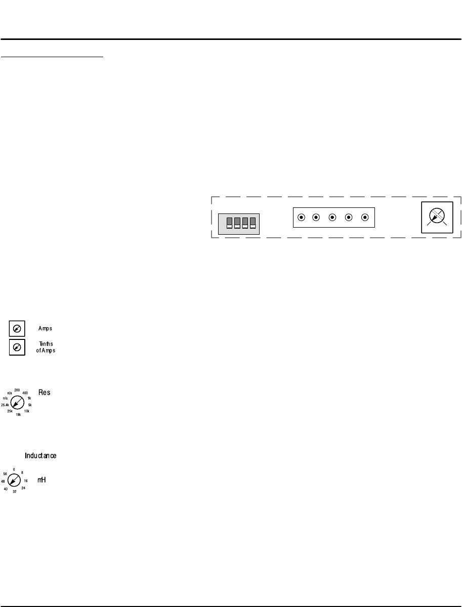
Motor Inductance (can be changed at any time)
Motor Inductance is set by a 16–position rotary range switch (Side Panel of Figure
3-4). The inductance switch has settings from 0 to 60 mH, in multiples of 4 mH.
For the proper setting, round motor inductance to the nearest multiple of 4 mH.
If the exact inductance of the motor is not known, initially set the inductance to
8mH. The inductance switch is more of an adjustment than a setting. If the setting
is too low, the motor will stall. If the setting is too high an audible hum will be heard
from the motor, and increase motor heating. Between these two extremes is
generally 2 or 3 correct inductance settings.