


3-4 Receiving & Installation MN1854
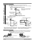
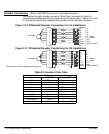
Table 3-1 Wire Size and Protection Devices
Incoming Power
Continuous Input
Input Fuse Wire Gauge
Catalog Number
Nominal Input
Voltage
Continuous
Output
Amps
(RMS)
Input
Breaker
(A)
Time
Delay (A)
AWG
(USA)
mm
2
(Europe)
LX2P1A06
115V (1f)
6.0A 20 20 14 2.5
Note: All wire sizes are based on 75°C copper wire. Higher temperature smaller gauge wire may
be used per NEC and local codes. Recommended fuses/breakers are based on 25°C
ambient, maximum continuous driver output current and no harmonic current.
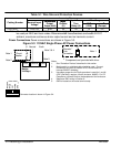
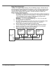
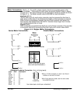
Power Connections Power connections are shown in Figure 3-3.
Figure 3-3 115VAC Single Phase AC Power Connections
Notes:
1. See “Protection Devices” described in this section.
2. Metal conduit or shielded cable should be used. Connect
conduits so the use of a Reactor or RC Device does not
interrupt EMI/RFI shielding.
3. Use same gauge wire for Earth ground as is used for L and N.
(VDE (Germany) requires 10mm
2
minimum, 6AWG). For CE
Compliance, connect Earth to the backplane of the enclosure.
4. Reference EMC wiring in Section 8.
5. GND is located on the motor terminal strip.
L1
Alternate *
Fuse
Connection
Note 1
L1 Neutral
Line Neutral
* Circuit
Breaker
Earth
Note 2
Note 1
Baldor
LinStep+
Note 3 & 4
* Components not provided with driver.
Earth
Note 5
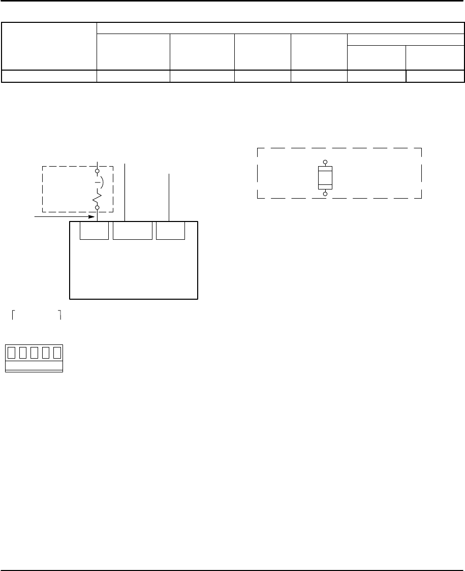
RPack
Line
RPack
Neutral
Earth
Power 110VAC
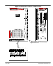
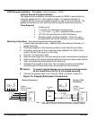
Connector location is shown in Figure 3-4.