


Receiving & Installation 3-11MN1854
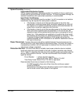
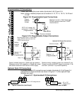
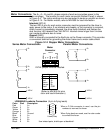
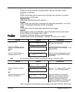
Motor Connections The A+, A–, B+ and B– phase outputs of each axis provides power to the
motor windings. The location for each motor connector (Bottom Panel) is shown
in Figure 3-4. The motor windings can be connected in series or parallel as shown
in Figure 3-14. For Baldor motors, refer to MN1800 for lead information.
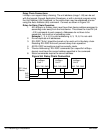
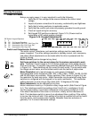
Interlock (INTLK)
The two INTLK pins for each motor connector must be jumpered for the drive to
apply power to the motor. If an interlock wire breaks, or the connector is removed,
motor current is immediately stopped, the drive faults (latched) and flashes the
dual function LED labeled Over Volt./INTLK. Interlock wires longer than 5 inches
can create shutdowns due to noise.
Ground (GND)
GND is internally connected to the Earth pin on the Power connector. This provides
a convenient terminal for grounding the motor frame and a motor cable shield.
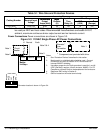
Figure 3-14 Stepper Motor Connections
B–
B+
A–
A+
INTLK
INTLK
Series Motor Connections
B–
Parallel Motor Connections
B+
A–
A+
INTLK
INTLK
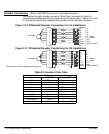
Motor
Color Phase
White
Red
Green
Orange
Black
A+
A–
B+
B–
GND
(Refer to MN1800 for wire
color and lead information.)
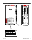
Motor
Connector
INTLK
INTLK
A+
A-
GND
B+
B-
Motor X
INTLK jumper must be installed.
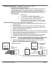
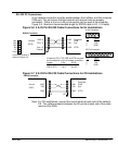
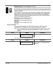
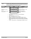
LD9068A00 Leadwire Connection (9 pin to flying leads)
1
2
3
4
5
6
7
8
9
Female (D Sub)
Color Pin# Description
Red 1 A+
Green 2 A–
Yellow 3 B+
Orange 4 B–
Black 5 Ground
Blue 6 A+
Green 7 A–
White 8 B+
Black 9 B–
When a D Sub connector is used, use the pin
numbers to connect the forcer.
When flying leads are used, use the color codes
to connect the forcer.
Use twisted pairs, shield open at backshell.