


Receiving & Installation 3-9MN1854
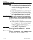
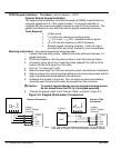
Programmable I/O Connections
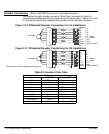
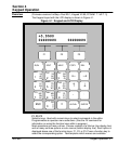
These input connections are made at terminals 6–40 (Figure 3-4).
Note: Factory installed jumpers are at locations 9–10, 13–14, 18–19, 19–20 and
21–22.
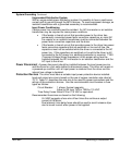
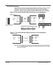
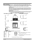
Figure 3-9 Programmable Input Connections
EOT1 & 2, Home1 & 2
and Inputs 1–8 (33–40)
(Programmable)
Opto Isolator
Common (Isolated)
1kÙ
Factory
Installed
Jumper
12V
P–Up
21
22
Maximum current = 35mA each input,
250mA maximum total from 12VDC
internal source.
Com 32
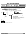
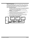
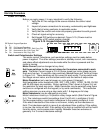
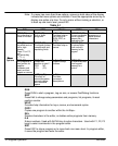
Figure 3-10 Programmable Output Connections
Outputs 1–8
(23–30)
(Programmable)
10kÙ
Opto
Isolator
12V
Factory installed jumper for 12VDC pull–up operation.
Maximum current sink capability is 100mA per output
and 350mA maximum from internal 12VDC supply.
P–Up
21
22
Maximum sink current = 100mA each
output, 250mA maximum total from
12VDC internal source.
Common
(Isolated)
Com 31
Factory
Installed
Jumper
Outputs 1–8
(Programmable)
Com
10kÙ
Opto
Isolator
(Remove Jumper)
12V
P–Up
External
+24VDC
Supply
+24V
Com
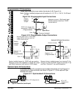
Optional 24V Output Connections
Remove factory installed jumper from terminal P–Up.
Connect an external 24VDC supply to terminals P–Up
and Com. (Terminal P–Up must be positive).
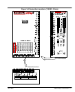
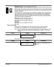
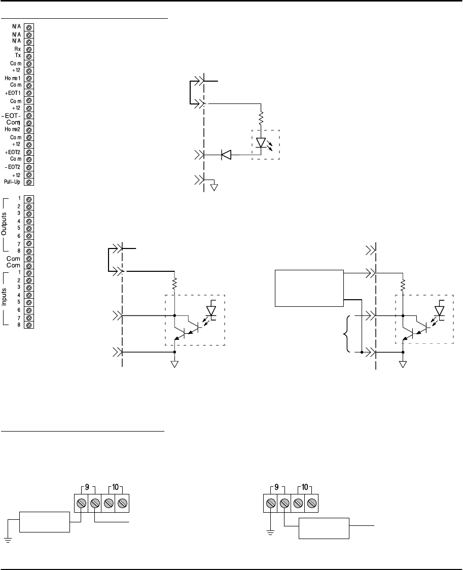
Optional Opto I/O Connections
8 Optically isolated I/O connections are located at terminals 9–16 of Figure 3-4.
Connections to these terminals are shown in Figure 3-11 (if the optional Opto
Modules are used).
Figure 3-11 Opto Isolated I/O Connections
User Output
Circuit
AC or +DC voltage source
Typical connection (each input)
User Load
Circuit
AC or +DC
voltage source
Typical connection (each output)