


3-111
Parallel I/O unit
3 Controller
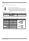
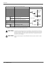
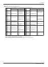
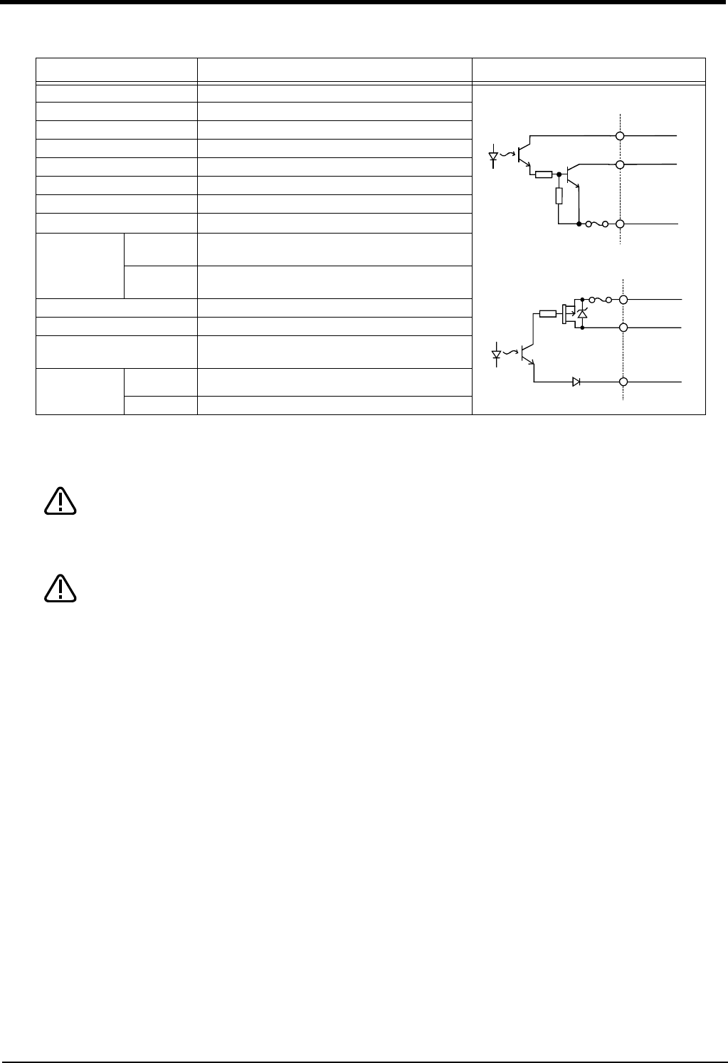
Table 3-24 : Electrical specifications for the output circuits
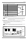
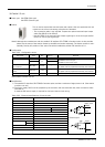
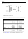
The output circuit protective fuses prevent failure in case of load short-circuit and
improper connections. Please do not connect loads that cause the current to exceed
the maximum rated current. If the maximum rated current is exceeded, the internal
transistors may be damaged.
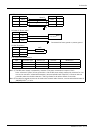
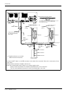
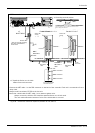
Inputs the power supply for control (DCcable-2) then inputs the controller’s power
supply.
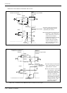
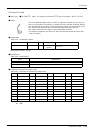
Item Specification Internal circuit
Type Transistor output
<Sink type>
<Source type>
No. of output points 32
Insulation method Photo-coupler insulation
Rated load voltage 12VDC/24VDC
Rated load voltage range 10.2 to 30VDC(peak voltage 30VDC)
Max. load current 0.1A/point (100%)
Leakage current at OFF 0.1mA or less
Max. voltage drop at ON
0.9VDC(TYP.)
Note1)
Note1) The maximum voltage drop value at signal ON.
Refer to it for the equipment connected to the output circuit.
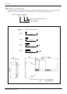
Response time
OFF-ON
2ms or less
(hardware response time)
ON-OFF
2ms or less
(Resistance load) (hardware response time)
Fuse rating Fuse 3.2A (one per common) Replacement not possible
Common method 8 points per common (common terminal: 4 points)
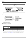
External wire connection
method
Connector
External power
supply
Voltage 12VDC/24VDC(10.2 to 30VDC)
Current 60mA (TYP. 24VDC per common) (base drive current)
+24V/+12V
出力
24G/12G
ヒューズ
Output
Fuse
+24V/+12V
24G/12G
出力
ヒューズ
Output
Fuse
CAUTION
CAUTION