


3 Controller
External I/O cable
3-122
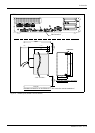
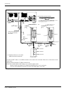
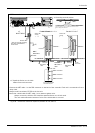
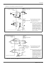
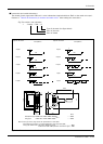
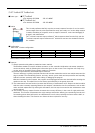
■ Connections and outside dimensions
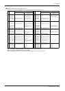
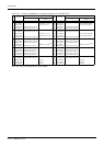
The sheath of each signal cable (50 lines) is color indicated and marked with dots. Refer to the cable color speci
-
fications in "Table 3-32: Connector pin numbers and cable colors" when making the connections.
Fig.3-41 : Connections and outside dimensions
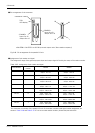
(Eg.) Pin number: color indication
1 : Orange / Red / A
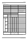
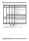
Type of dot mark (see figure below)
Color of dot mark
Color of sheath
Type of dot mark
A type
B type
C type
D type
E type
F type
G type
H type
I type
J type
Dot pattern
Receptacle type (PCB side):57AE-40500-21D(D8)
Plug type (cable side):57YE-30500-2(D8)
……DDK
Maker
……DDK
26
5000
6
6
50
25
1
18.5
1
18.5
18.5
Continuous
18.5
1.5
1.5
1.5
1.5
18.5
3
3
3
18.5
18.5
18.5
7.5
7.5
Continuous
35.7
13.54
16.2
9.27
7
6
.
7
4
6
4
.
5
3
5
1
.
8
1
6
2
.
1
5
9
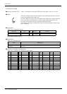
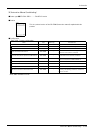
Type of dot mark
Dot pattern
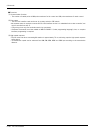
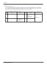
Note1) The type of the plug shows the specification of this cable.
The following connector is recommended when user make the cable.
・Plug type (cable side) : 57E series (Soldering type).....................................................DDK
57FE series (Flat cable pressure connection type)......DDK
Note1)