2-39
Tooling
2 Robot arm
2.5.6 About the Installation of Tooling Wiring and Piping (Examples of Wiring and Piping)
The customer is required to provide tooling wiring, piping and metal fixtures.
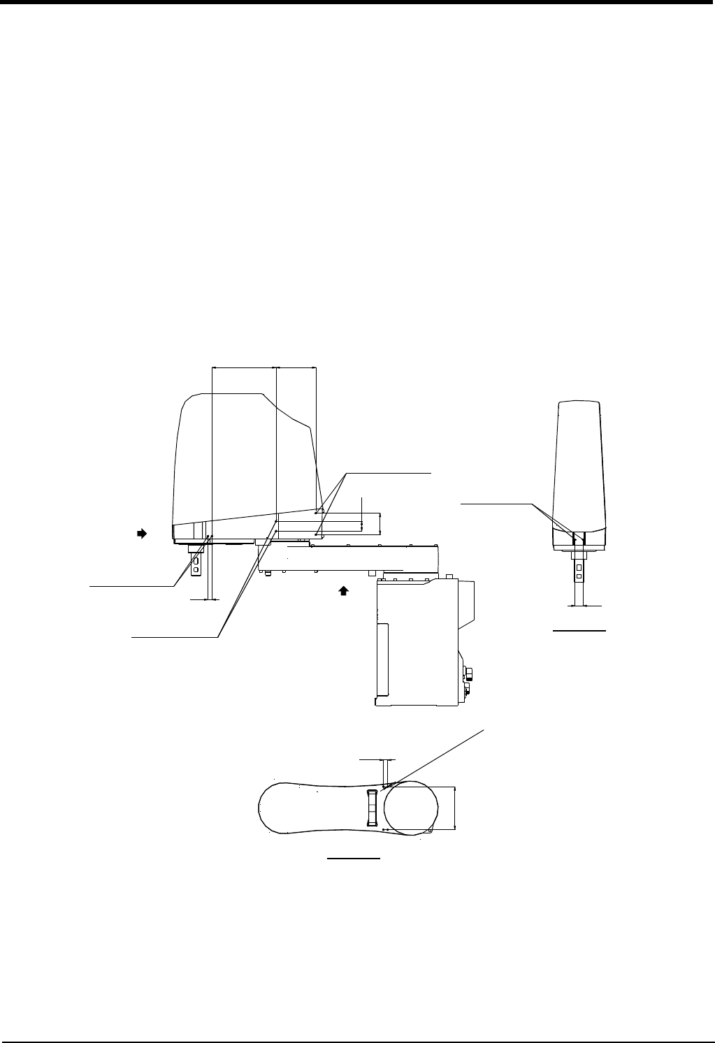
Screw holes are provided on the robot arm for the installation of tooling wiring, piping and metal fixtures. (Refer to
the Fig. 2-24.)
The length of wiring and piping and the installation position on the robot must be adjusted according to the work
to be done by the robot. Please use the following example as reference.
<Precautions>
・ A hand input cable and a hand curl cable are available as optional accessories for your convenience.
・ After performing wiring and piping to the robot, operate the robot at low speed to make sure that each part
does not interfere with the robot arm and the peripheral devices.
Confirm that there is no interference also with bellows of the shaft section by clean specification .
・ Please be aware that dust may be generated from friction if wires and pipes come into contact with the robot
arm when using it according to the clean specifications.
・If you install metal fixtures and a solenoid valve using the screw holes on the No.2 arm portion, add the mass of
the metal fixtures and the solenoid valve to mass of a hand then set the HNDDAT parameter. Moreover, Fix
the parts, such as a solenoid valve, firmly to prevent the parts getting shaky during operation of a robot.
Fig.2-24 : Location of screw holes for fixing wiring/piping
164 102
2-M4深さ6
(反対側にもあり)
10
2-M4深さ8
(反対側にもあり)
2-M4深さ8
(反対側にもあり)
25
55
2-M4深さ8
20
11
110
4
-
M5
ね
じ
深
さ
1
1
B
矢視B
A
矢視A
(Usable on opposite
side too.)
2-M4, depth 8
View B
View A
4
-
M
5
s
c
r
e
w
,
d
e
p
t
h
1
1
2-M4, depth 8
(Usable on opposite
side too.)
2-M4, depth 6
2-M4, depth 8
(Usable on opposite
side too.)


