


2 Robot arm
2-14
2.2.2 Mass capacity
The robot's mass capacity is expressed solely in terms of mass, but even for tools and works of similar mass,
eccentric loads will have some restrictions When designing the tooling or when selecting a robot, consider the fol-
lowing issues.
(1) The tooling should have the value less or equal than the smaller of the allowable moment of inertia found in
Page 9, "2.1.1 Basic specifications".
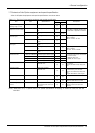
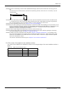
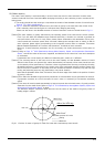
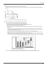
(2) Fig. 2-1 shows the distribution dimensions for the center of gravity in the case where the volume of the
load is relatively small. Use this figure as a reference when designing the tooling.
Please use the robot in the allowable moment of inertia of maximum moment of inertia shown in Fig. 2-1.
[Caution]The mass capacity is greatly influenced by the operating speed of the robot and the motion posture.
Even if you are within the allowable range mentioned previously, a vibration, an overload or generate an
overcurrnt alarm could occur. In such cases, please reduce acceleration and deceleration (Accel com-
mand) speeds and movement speed (Ovrd command). Although the standard value to reduce is 50% for
each command, please adjust corresponding to the movement posture. Refer to separate "Instruction
Manual/Detailed Explanation of Functions and Operations" for details of each command.
Moreover, if hand/workpiece parameters are not set exactly, the similar phenomenon will be easier to
occur.
[Caution] Refer to Page 15, "2.2.3 Relationships Among Mass Capacity, Speed, and Acceleration/Deceleration
Speed", and set the values of the mass, magnitude, and distance to the centroid of a tool and a workpiece
to parameters.
If parameters are not set exactly, the lifetime of reduction gears, a belt, etc. is affected.
[Caution] The overhang amount of the load, such as the mass capacity and the allowable moment of inertia
defined in this section, are dynamic limit values determined by the capacity of the motor that drives axes
or the capacity of the speed reducer. Therefore, it does not guarantee the accuracy on all areas of tooling.
Guaranteed accuracy is measured from the center point of the mechanical interface surface. Please note
that if the point of operation is kept away from the mechanical interface surface by long and low-rigid
tooling, the positioning accuracy may deteriorate or may cause vibration.
Note that the allowable offset value (Z direction) from the lower edge of the shaft to the position of center
of gravity is 100 mm.
[Caution] Even within the allowable range previously mentioned, an overload alarm may be generated if an ascend-
ing operation continues at a micro-low speed. In such a case, it is necessary to increase the ascending
speed.
[Caution] This robot will restrict speed automatically by internal controls when the load center-of-gravity position
separates from the shaft center. Refer to Page 15, "2.2.3 Relationships Among Mass Capacity, Speed, and
Acceleration/Deceleration Speed" in detail.
The allowance distance (allowance offset amount) from the center of the shaft to the gravity center of
loading weight is 100mm.
Fig.2-1 : Position of center of gravity for loads (for loads with comparatively small volume)
定格慣性モーメント
最大慣性モーメント
シャフト中心
単位:mm
20mm(1kg)
100mm(3kg以下)
Unit: mm
Shaft center
Allowable moment of inertia
Maximum
Rating
100mm (less than 3kg)