2-35
Outside dimensions ・ Operating range diagram
2 Robot arm
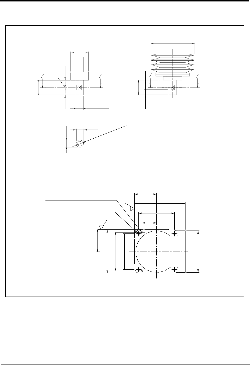
2.4.2 Mechanical interface and Installation surface
Fig.2-22 : Mechanical interface and Installation surface
<ハンド取り付けフランジ部詳細>
<ベース裏面据付寸法詳細>
92
92
90 120
150
60
2-φ6穴
(φ8位置決めピン用下穴)
4-φ9据付用穴
(据付基準)
(据付基準)
Rz25
Rz25
180
150
174
断面Z-Z
15
15
φ
1
1
貫
通
穴
φ16h7
φ37.5
30
10
10
10
φ90
10
30
10
クリーン仕様
標準仕様
160
<Detail of Mechanical interface>
Standard specification Clean specification
Section Z-Z
φ
1
1
t
h
r
o
u
g
h
h
o
l
e
<Details of installation dimensions>
4-φ9 installation reference hole
(Installation reference surface)
(Installation
reference surface)
2-φ6 hole
Pilot hole (positioning pin φ8)
Note) Don't install the robot arm in the position where direct rays or the heat of lighting hits. The skin temperature of the
robot arm may rise, and the error may occur.


