


2-27
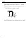
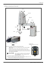
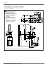
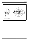
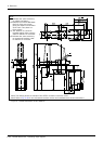
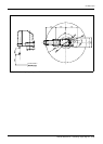
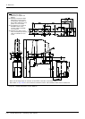
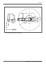
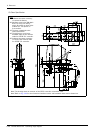
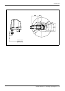
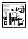
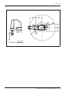
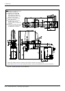
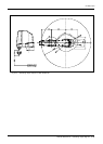
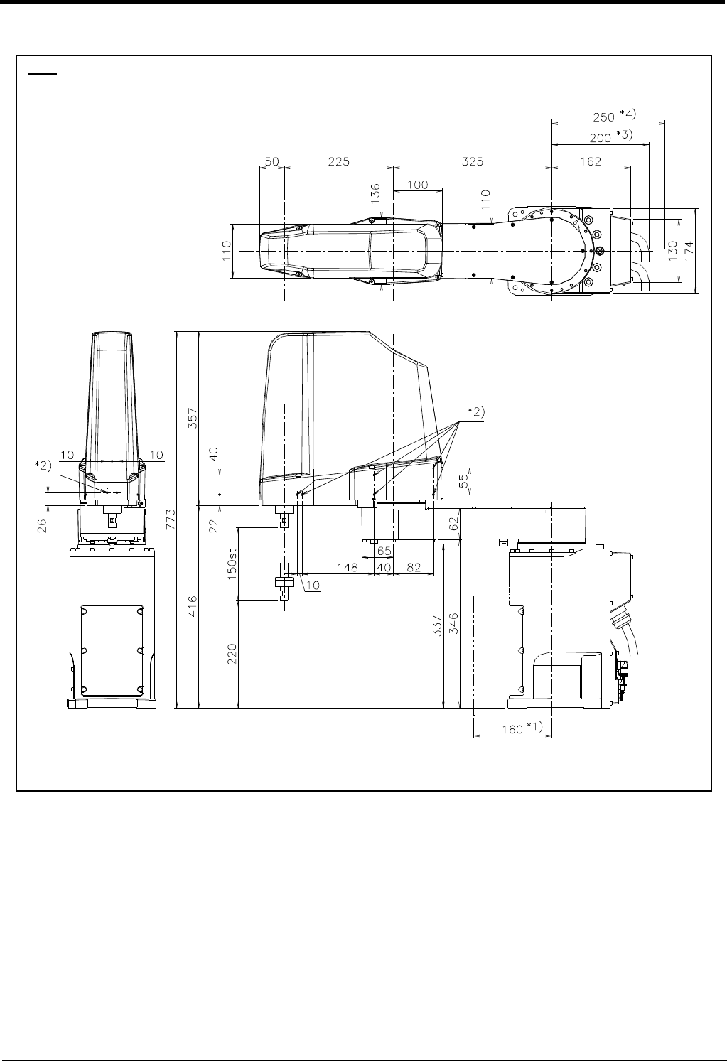
Outside dimensions ・ Operating range diagram
2 Robot arm
Fig.2-14 : Outside dimensions of RH-3FH5515
Note
*1) Indicates the space
necessary to replace the
battery.
*2) Indicates screw holes (M4
depth 6mm) for fixing user
wiring/piping. Six places on
both-sides of No.2 arm, Two
places on front surface.
*3) The distance to a minimum
bendable radius of the
machine cable for CR750/
751 controller.
*4) Indicates the space neces-
sary to connect the machine
cable for CR750/751 con-
troller.
Note) The drawing shows an example of the CR751 controller connection robot.
Note) Refer to Fig. 2-22 for the mechanical interface section and installation base section dimensions.