


6-147
Safety
6Safety
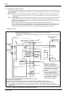
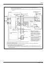
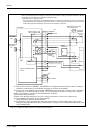
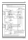
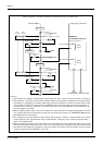
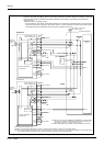
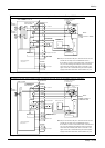
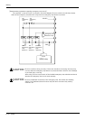
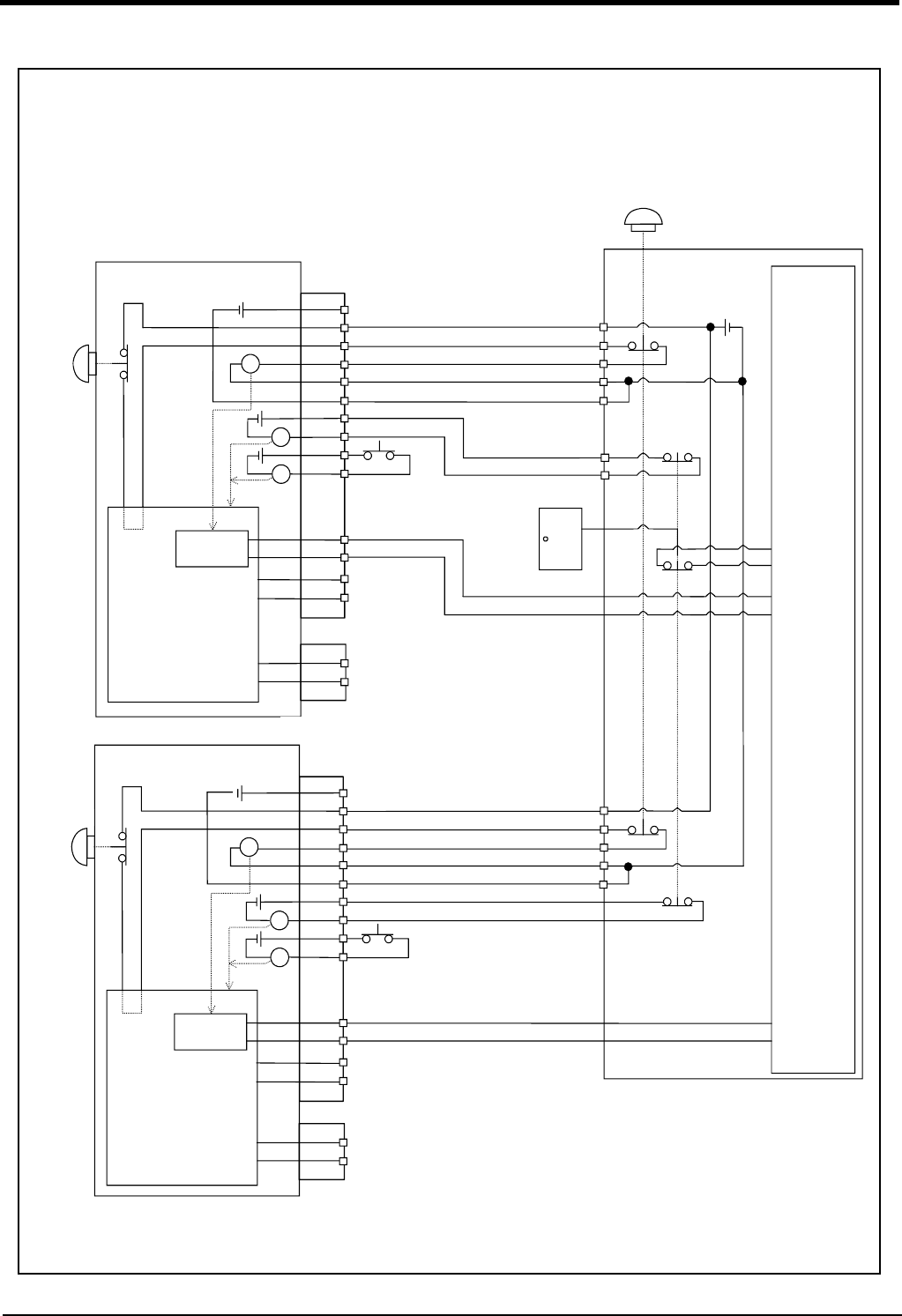
Fig.6-9 : Example of safety measures (CR751 wiring example 4)
周辺装置
の非常停止
出力
周辺装置内部
非常停止回路
周辺装置
非常停止スイッチ
(4接点タイプ)
安全柵のドア
ドアスイッチ出力
監視
周辺装置
の非常停止
出力
周辺装置側
電源24V
1/ 6
CNUSR1
CNUSR2
内部非常停止回路
コントローラ #1
未接続
非常停止出力
モード出力
TB非常停止
ボタン
RA
RA
RA
}
内部電源 24V
ドアスイッチ入力
イネーブリング
デバイス
26/31
2/ 7
27/32
3/ 8
28/33
4/ 9
29/34
5/10
30/35
16/17
41/42
エラー出力
}
監視
監視
1/ 6
CNUSR1
CNUSR2
内部非常停止回路
コントローラ #2
未接続
非常停止出力
モード出力
TB非常停止
ボタン
RA
RA
RA
}
ドアスイッチ入力
イネーブリング
デバイス
26/31
2/ 7
27/32
3/ 8
28/33
4/ 9
29/34
5/10
30/35
16/17
41/42
エラー出力
}
20/19
45/44
18/17
43/42
20/19
45/44
18/17
43/42
安全リレー
安全リレー
内部電源 24V
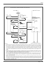
Controller #1
Power supply in the
robot controller 24V
TB emer-
gency stop
button
Not connected
Door switch input
Enabling
device
Mode output
Error output
Emergency stop output
Safety relay
Internal emergency
stop circuit
Emergency stop switch
(2- contact type)
Safety fence door
Power supply
24V
*1)
*1)
*3)
*4)
*5)
Peripheral equipment
*3) Emergency stop input relay.
*4) Refer to the Standard specification manual or the Special specification manual for the enabling device.
*5) The emergency stop input detection relay uses the controller’s internal safety relay control. If the emergency stop input detection
relay is switched OFF, emergency stop is detected and the safety relay is also switched OFF.
*2)
Monitor
Monitor
<Wiring example 4>: Connect the emergency stop switch of peripheral equipment, and the door switch to two controllers, and it
interlocks. Connect the enabling device to the robot controller.The power supply for emergency stop input
uses the power supply of peripheral equipment. Monitor the emergency stop state by the peripheral
equipment side.
<Operation of the emergency stop>
If the emergency stop switch of peripheral equipment is pushed, the robot will also be in the emergency
stop state. And, if the emergency stop switch of OP or T/B is pushed in the state of the power of con
-
troller OFF, peripheral equipment state can be the emergency stop also.
*1)
*1)
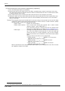
Controller #2
TB emer-
gency stop
button
*2)
Power supply in the
robot controller 24V
Not connected
Door switch input
Mode output
Error output
Safety relay
*5)
Internal emergency
stop circuit
Enabling
device
*4)
Emergency stop output
Circuit
Monitor
*3)
*1) Each of the connectors, CNUSR1 and CNUSR2, are assigned with
the same pin number, creating 2 systems in each terminal. It is
absolutely necessary to connect the 2 systems.
*2) The T/B emergency stop button connected with the controller.
*3)