


6-137
Safety
6Safety
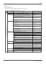
6.1.2 External input/output signals that can be used for safety protection measures
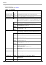
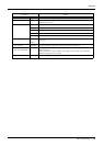
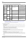
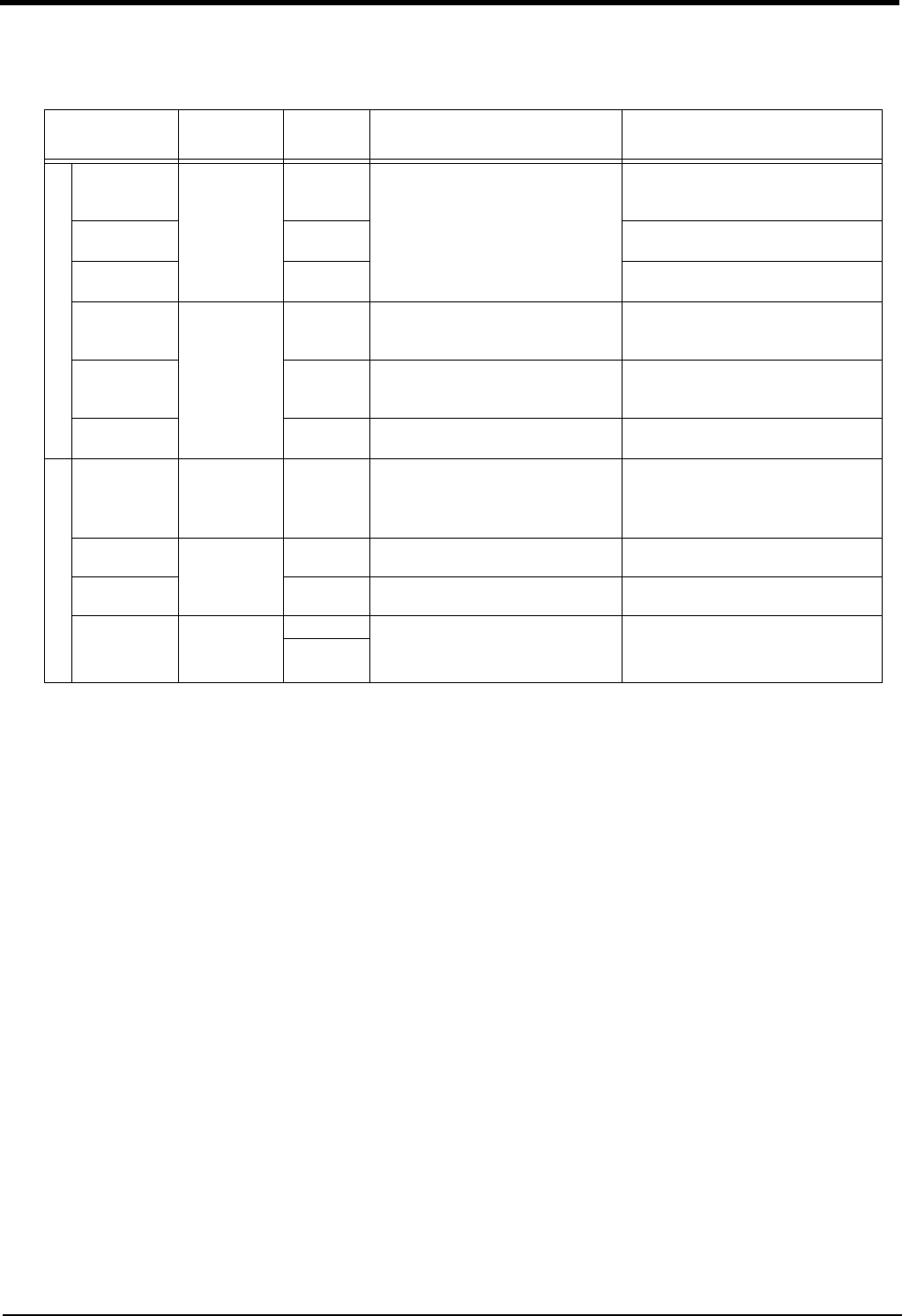
Table 6-3 : External input/output signals that can be used for safety protection measures
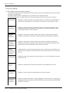
6.1.3 Precautions for using robot
The safety measures for using the robot are specified in the "Labor Safety and Sanitation Rules". An outline of
the rules is given below.
(1) Robot installation
・ Secure sufficient work space required to safely perform work such as teaching and maintenance related to the
robot.
・ Install the controller outside the robot's motion space. (If a safety fence is provided, install outside the fence.)
・ Install the controller where the entire robot operation can be viewed.
・ Install display lamps, etc., to indicate the robot's operation state.
・ Securely fix the robot arm onto the fixing table with the designated bolts.
(2) Prevention of contact with operator
・ Install a safety fence or enclosure so that the operator cannot easily enter the robot's motion space.
・ Install an interlock function that will stop the robot if the safety fence or enclosure door is opened.
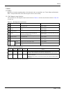
(3) Work procedures
・ Create and observe work procedures for the robot teaching, operation, inspection and emergencies.
・ Create hand signals to be followed when several operators are working together.
・ Create displays such as "Teaching in Progress" and "Inspection in Progress" to be put up when an operator is
in the robot's motion space so that other operators will not operate the operation panel (controller, control
panel).
(4) Training
・ Train the operators about the operations, maintenance and safety required for the robot work.
Signal
Connection
point
Parameter Functions Usage method
Input
External emer-
gency stop
Note1)
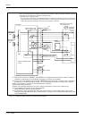
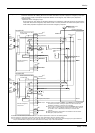
Note1) The external emergency stop input is prepared as a normal close for safety proposes. Thus, if the emergency stop
input circuit is opened when the robot is started up, the robot will not operate. Refer to Page 139, "6.1.7 Exam
-
ples of safety measures"for details.
And, refer to Page 90, "(3) Automatic Operation/Jog Operation/Brake Release and Necessary Switch Set
-
tings"for the function of the door switch input and the enabling device input.
Connector
(CR750 controller:
CNSUSR11/12)
(CR751 controller:
CNSUSR1)
- This servo power is shut off, and the
robot stops immediately.
Externally installed emergency stop switch.
Door switch on safety protection fence.
Stopping at high-level error occurrence.
Door switch - The door switch of the safe protection
fence
Enabling device
input
- Enabling device.
The safety switch during teaching work
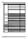
Stop Parallel I/O unit
or interface
STOP The program execution is stopped, and
the robot stops. The servo power is not
shut off.
The robot is stopped when a peripheral
device fault occurs. The servo power is
not shut off.
Servo OFF SRVOFF The servo power can be shut off. The robot is stopped when a peripheral
device fault occurs. The servo power is
not shut off.
Automatic oper
-
ation enable
AUTOENA Disables automatic operation when inac
-
tive.
Door switch on safety protection fence
Output
Emergency stop
output
Connector
(CR750 controller:
CNSUSR11/12)
(CR751 controller:
CNSUSR1)
- Outputs the input signal of external
emergency stop or emergency stop
switch of T/B turned on.
Display and warn the pilot lamp, the input
signal of external emergency stop or the
emergency stop switch of T/B turned on.
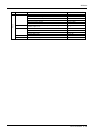
In servo ON Parallel I/O unit
or interface
SRVON The servo power ON/OFF state is out
-
put.
The servo power ON/OFF state is shown
and alerted with the display lamps.
Waiting STOP Outputs that the robot is temporarily
stopped.
The temporary stop state is shown and
alerted with the display lamps.
In alarm Connector
CR750/CR751
controller:
(CNUSR2)
ERRRESET Outputs when an alarm occurs in the
robot.
The alarm state is shown and alerted with
the display lamps.
-