


2 Robot arm
2-16
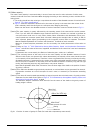
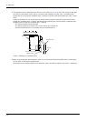
2.2.5 Vibration of shaft (J3 axis) position and arm end
Vibrations at the tip of the arm may increase substantially during operation under the shaft position near the
low end or the high end of the robot, depending on the combination of hand mass and hand inertia. This problem
occurs according to that inertia, because the distance from the shaft support section to the shaft end becomes
long. When this vibration affects the robot's operations, please change operating speed etc. like the above Page
15, "2.2.4 Vibrations at the Tip of the Arm during Low-Speed Operation of the Robot".
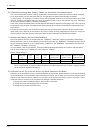
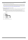
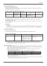
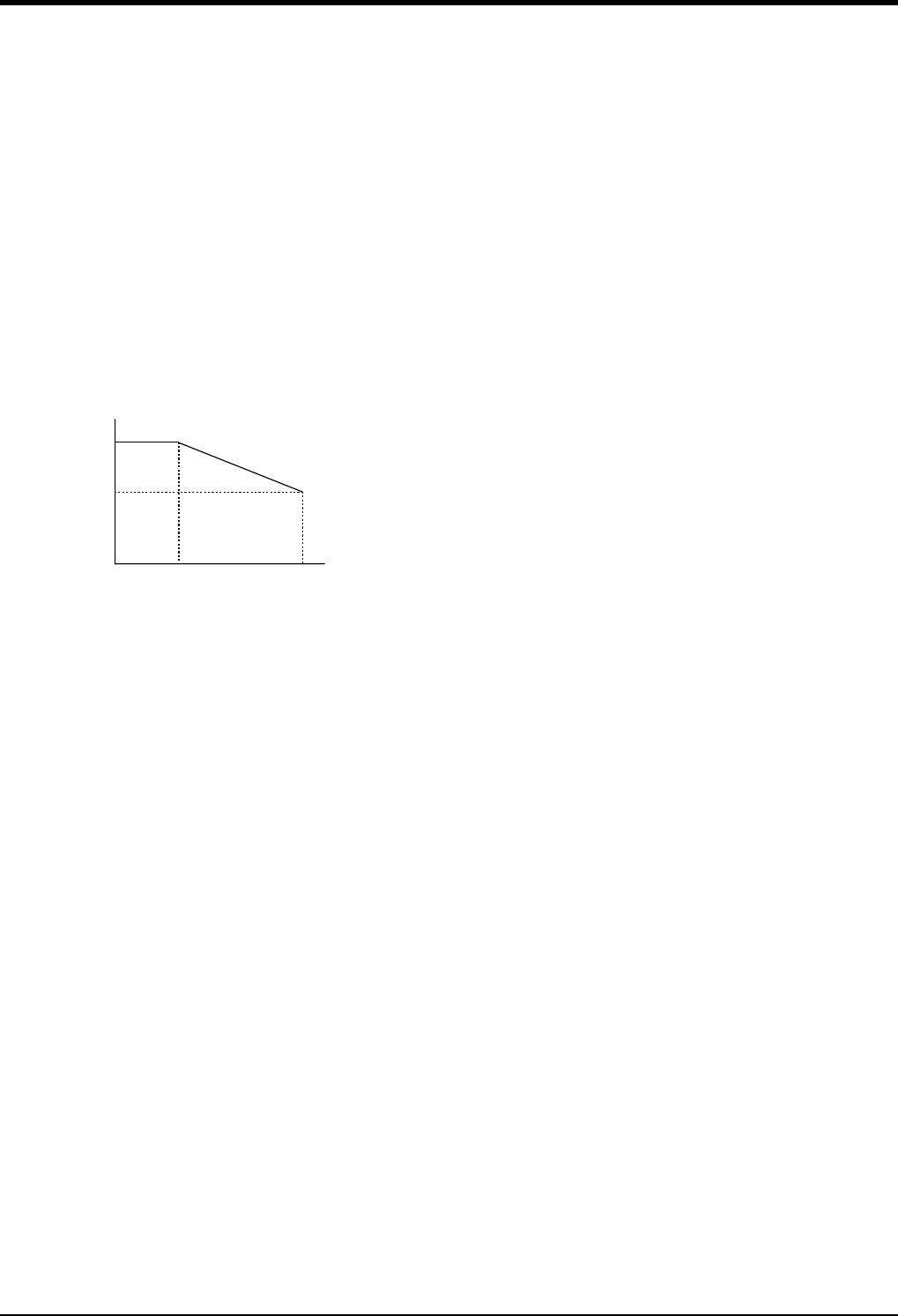
(1) Relationship Between Mass Capacity and Speed
A function to optimize the maximum speed of each axis according to the setting value of the load capacity will be
activated (Refer to Fig. 2-2).
However, this function does not work with the setting of 1kg or lighter load mass. When the setting of the load
mass is changed to 1kg or heavier, the maximum speed is compensated according to the load mass.
[CAUTION] Depending on the operation pattern, the speed and/or acceleration/deceleration at the front edge
may not be parallel with the speed and the rate of change of acceleration/deceleration specified in a
program.
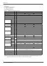
Fig.2-2 : Automatic compensation of speed
100
60
0
0
1
負荷質量(kg)
3
(%)
RH-3FH series
Maximum speed ratio (%)
Load capacity (kg)