


3-79
Emergency stop input and output etc.
3 Controller
3.6 Emergency stop input and output etc.
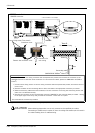
Do wiring of the external emergency stop, the special stop input, the door switch, and the enabling device from
the "special input/output" terminal connector.
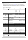
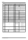
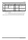
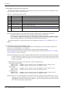
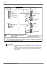
Table 3-3 : Special input/output terminal
*At the time of the power supply OFF, the output point of contact is always open.
[Note] The contact capacity of each input/output terminal is DC24V/10mA - 100mA. Don't connect the
equipment except for this range. The use exceeding contact capacity causes failure.
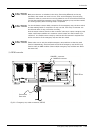
In the customer's system, do not ground the + side of 24V power supply prepared by customer for connect
to the controller. (related with emergency stop and parallel input/output) If it connects with the controller
under the condition that the + side is grounded, it will lead to failure of controller.
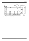
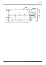
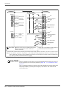
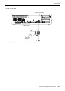
Pin number assignment of each terminal and the circuit diagram are shown in Fig. 3-14 (CR750) or Fig. 3-13
(CR751).
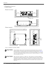
3.6.1 Connection of the external emergency stop
The external emergency stop input and door switch input and enabling device input are opened at shipment as
shown in Fig. 3-14 (CR750) or Fig. 3-13 (CR751).
Connect the external emergency stop switch and door switch with the following procedure.
And, the example of the connection and notes of the emergency stop are described in Page 139, "6.1.7 Examples
of safety measures" Refer to it together
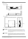
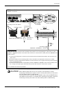
[Caution] The emergency stop circuit is duplicated inside the controller. The emergency stop switch uses a double
contact-type switch, so please be sure to fix both of the contacts to the connector pins as shown below
in order to ensure the wiring is duplicated. An error will continue to occur in the event that only one of
the pins is connected.
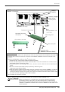
1) Please prepare the emergency stop switch, door switch and enabling device.
a) External emergency switch
・ CR750 controller...........CNUSR11 connector "between 3 and 4" and CNUSR12 Connector "between 3 and 4".
・ CR751 controller...........CNUSR1 connector "between 2 and 27" and "between 7 and 32".
b) Door switch
・ CR750 controller...........CNUSR11 connector "between 7 and 8" and CNUSR12 connector "between 7 and 8".
・ CR751 controller...........CNUSR1 connector "between 4 and 29" and "between 9 and 34".
c) Enabling device
・ CR750 controller...........CNUSR11 connector "between 9 and 10" and CNUSR12 connector "between 9 and 10".
・ CR751 controller...........CNUSR1 connector "between 5 and 30" and "between 10 and 35".
[Caution] Be sure to use a shield cable for the emergency stop wiring cable. And when operating in an environ-
ment that is easily affected by noise, be sure to fix the attached ferrite core (model number:
E04SR301334, manufacturer: Seiwa Electric Mfg. Co., Ltd.). Be sure to place the ferrite core more than
30 cm from the connecting terminal section.
Item Name Function
Input Emergency stop Applies the emergency stop. Dual emergency line
Input Special stop input Applies the stop. (Refer to Page 87, "3.6.2 Special stop input (SKIP)")
Input Door switch Servo-off. Dual line, normal close (Page 89, "3.6.3 Door switch function")
Input Enabling device Servo-off. Dual line, normal close (Page 89, "3.6.4 Enabling device function")
Output Robot error output Contactor is opening during error occurrence.
Output Emergency stop output The point of contact opens under occurrence of emergency stop of external input signal, emergency
stop of OP, emergency stop of T/B.
Output Mode output MANUAL mode: contactor is opening, AUTOMATIC mode: contactor is closing.
Output Magnet contactor control
connector output for addi-
tion axes
When an additional axis is used, the servo ON/OFF status of the additional axis can be synchronized
with the robot arm. (Page 97, "3.9 Magnet contactor control connector output (AXMC) for addition
axes")