


3-121
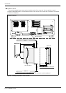
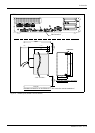
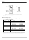
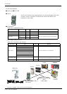
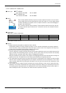
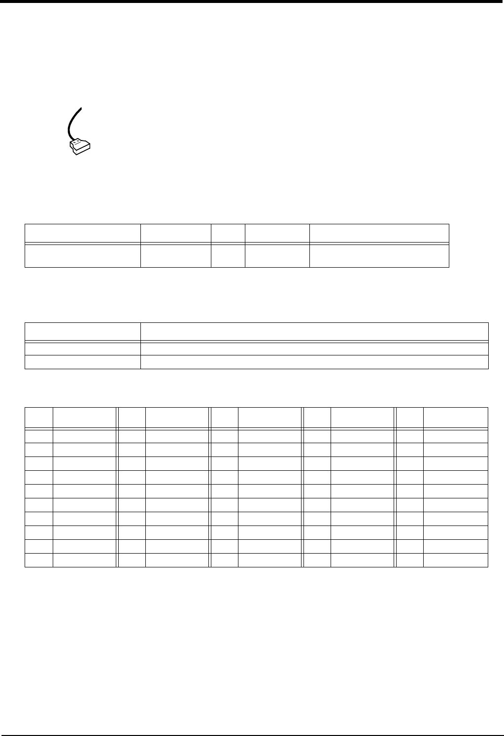
External I/O cable
3 Controller
(5) External I/O cable
■ Order type: 2A-CBL □□ Note) The numbers in the boxes □□ refer to the length. (05: 5m、 15: 15m)
■ Outline
This is the dedicated cable used to connect an external peripheral device to the con
-
nector on the parallel input/output unit.
One end matches the connector on the parallel input/output unit, and the other end
is free. Connect the peripheral device's input/output signal using the free end.
One cable correspond to the input 16 points and output 16 points.
Two cables are needed to connection of (input 32 points and output 32 points) with
built-in standard.
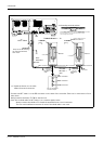
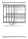
■ Configuration
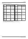
Table 3-30 : Configuration device
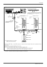
■ Specifications
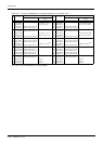
Table 3-31 : Specifications
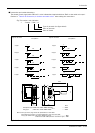
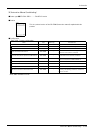
■ Connector pin numbers and cable colors
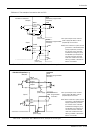
Table 3-32 : Connector pin numbers and cable colors
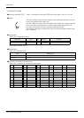
Part name Type Qty.
Mass(kg)
Note1)
Note1) Mass indicates one set.
Remarks
External I/O cable 2A-CBL □□ 1pc. 0.7(5m)
1.84(15m)
5m or 15m
Items Specifications
Number of cables x cable size 50 pairs x AWG #28
Total length 5m or 15m
Pin
no.
Cable colors
Pin
no.
Cable colors
Pin
no.
Cable colors
Pin
no.
Cable colors
Pin
no.
Cable colors
1 Orange/Red A 11 Orange/Red C 21 Orange/Red E 31 Orange/Blue B 41 Orange/Blue D
2 Gray/Red A 12 Gray/Red C 22 Gray/Red E 32 Gray/Blue B 42 Gray/Blue D
3 White/Red A 13 White/Red C 23 White/Red E 33 White/Blue B 43 White/Blue D
4 Yellow/Red A 14 Yellow/Red C 24 Yellow/Red E 34 Yellow/Blue B 44 Yellow/Blue D
5 Pink/Red A 15 Pink/Red C 25 Pink/Red E 35 Pink/Blue B 45 Pink/Blue D
6 Orange/Red B 16 Orange/Red D 26 Orange/Blue A 36 Orange/Blue C 46 Orange/Blue E
7 Gray/Red B 17 Gray/Red D 27 Gray/Blue A 37 Gray/Blue C 47 Gray/Blue E
8 White/Red B 18 White/Red D 28 White/Blue A 38 White/Blue C 48 White/Blue E
9 Yellow/Red B 19 Yellow/Red D 29 Yellow/Blue A 39 Yellow/Blue C 49 Yellow/Blue E
10 Pink/Red B 20 Pink/Red D 30 Pink/Blue A 40 Pink/Blue C 50 Pink/Blue E