


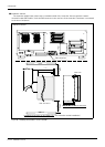
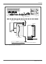
3 Controller
Parallel I/O unit
3-118
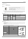
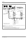
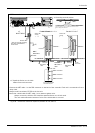
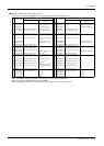
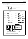
■ Parallel I/O interface (First expansion unit)
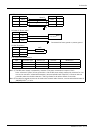
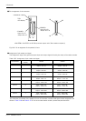
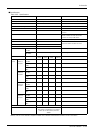
Table 3-26 : Connector CN100pin No. and signal assignment list (2A-CBL
□□ )
Pin
No.
Line color
Function name
Pin
No.
Line color
Function name
General-purpose
Dedicated/power supply,
common
General-purpose
Dedicated/power supply,
common
1 Orange/Red A FG 26 Orange/Blue A FG
2 Gray/Red A 0V:For pins 4-7, 10-13 27 Gray/Blue A 0V:For pins 29-32, 35-38
3 White/Red A 12V/24V:For pins 4-7 28 White/Blue A 12V/24V:For pins 29-32
4 Yellow/Red A General-purpose output 0
Operating output
Note1)
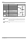
Note1) The dedicated signal is assigned at shipping. It can change with the parameter.
29 Yellow/Blue A General-purpose output 4
5 Pink/Red A General-purpose output 1 In servo ON output signal
Note1)
30 Pink/Blue A General-purpose output 5
6 Orange/Red B General-purpose output 2 Error occurring output signal
Note1)
31 Orange/Blue B General-purpose output 6
7 Gray/Red B General-purpose output 3 Operation rights output sig
-
nal
Note1)
32 Gray/Blue B General-purpose output 7
8 White/Red B 0V:For pins 4-7, 10-13 33 White/Blue B 0V:For pins 29-32, 35-38
9 Yellow/Red B 12V/24V:For pins 10-13 34 Yellow/Blue B 12V/24V:For pins 35-38
10 Pink/Red B General-purpose output 8 35 Pink/Blue B General-purpose output 12
11 Orange/Red C General-purpose output 9 36 Orange/Blue C General-purpose output 13
12 Gray/Red C General-purpose output 10 37 Gray/Blue C General-purpose output 14
13 White/Red C General-purpose output 11 38 White/Blue C General-purpose output 15
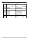
14 Yellow/Red C COM0:For pins 15-22
Note2)
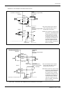
Note2) Sink type:12V/24V(COM),Source type:0V(COM)
39 Yellow/Blue C COM1:For pins 40-47
Note2)
15 Pink/Red C General-purpose input 0
Stop input
Note3)
Note3) The dedicated input signal (STOP) is assigned at shipping. The signal number is fixing.
40 Pink/Blue C General-purpose input 8
16 Orange/Red D General-purpose input 1 Servo OFF input signal
Note1)
41 Orange/Blue D General-purpose input 9
17 Gray/Red D General-purpose input 2 Error reset input signal
Note1)
42 Gray/Blue D General-purpose input 10
18 White/Red D General-purpose input 3
Start input
Note1)
43 White/Blue D General-purpose input 11
19 Yellow/Red D General-purpose input 4
Servo ON input signal
Note1)
44 Yellow/Blue D General-purpose input 12
20 Pink/Red D General-purpose input 5 Operation rights input sig
-
nal
Note1)
45 Pink/Blue D General-purpose input 13
21 Orange/Red E General-purpose input 6 46 Orange/Blue E General-purpose input 14
22 Gray/Red E General-purpose input 7 47 Gray/Blue E General-purpose input 15
23 White/Red E Reserved 48 White/Blue E Reserved
24 Yellow/Red E Reserved 49 Yellow/Blue E Reserved
25 Pink/Red E Reserved 50 Pink/Blue E Reserved