2 Robot arm
Names of each part of the robot
2-22
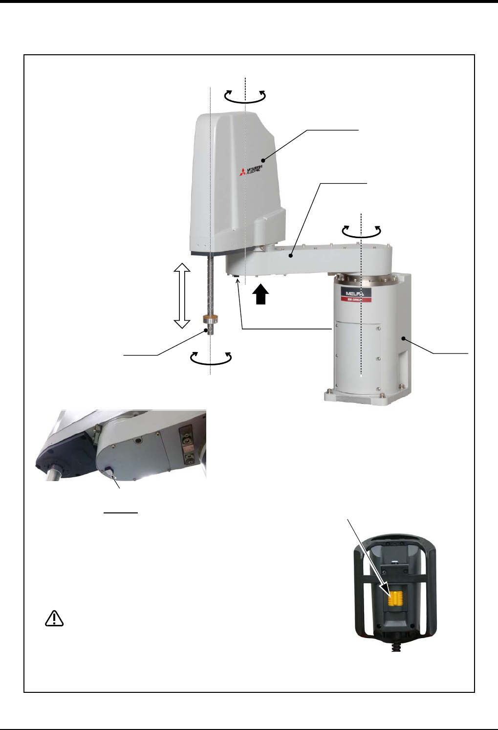
2.3 Names of each part of the robot
Fig.2-9 : Names of each part of the robot
ベース
第2アーム
J4軸
+
-
J2軸
+
-
J1軸
+
-
第1アーム
J3軸
+
-
シャフト
ブレーキ解除スイッチ
ブレーキ解除スイッチ
View A
Note 1) The operation method of the brake release switch.
The brake of J3 axis can be released with this switch and the enabling
switch of T/B.
Please be sure to perform brake release operation by two-person
operations. Always assign an operator other than the switch operator to
prevent the arm from dropping. This operation must be carried out with the
switch operator giving signals.
When releasing the brake the J3 axis will drop. Be
sure to perform brake release operation by two-
person operations.
(1) One person supports so that the J3 axis may not drop.
(2) The one more person pushes the brake release switch of the robot arm, in the
condition that the enabling switch of T/B is turned on.
CAUTION
Brake release switch
No.1 arm
No.2 arm
J1 axis
J2 axis
Base
J3 axis
Shaft
J4 axis
T/B
Enabling switch
(Hold down to the left or the right.)
Brake release switch
A
Note1)


