


VILTER MANUFACTURING CORPORATION
VILTER MultiCylinder Compressor
SERVICE SECTION
ILLUSTRATIONS AND TABLES
PAGE
FIGURE
3 1 Bearing And Cylinder Covers Assembly & Disassembly Stud
5 2 Upper Cylinder Cross Section
6 3 Discharge Diaphragm Valve Placement
8 4 Flywheel Removal Tool
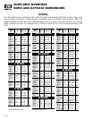
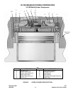
9 5 Unit Belting Requirements Due To Horsepower
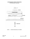
11 6 Belt Tension Spring Scale
13 7 Typical Capacity Control Mechanism Arrangement – 440 Compressor (Old Style Mushroom
Type)
15 8 Typical Capacity Control Mechanism Arrangement – 450 & 450XL Compressor (New Style
Bulletin Type)
16 9 Safety Valve Location
20 10 Piston Ring Compressing Tool
21 11 Front Cover Assembly And Disassembly Tool
22 12 Crankshaft Seal Assembly
23 13 Piston Ring Dimensions
24 14 Cylinder Liner Assembly Tool
24 15 Cylinder Liner Removal Tool
27 16 Retainer Partial Vertical Cross Section
36 17 Typical 400 Series Compressor Vertical Cross Section and Lubricating System
PAGE
TABLE
23 1 Piston Ring Dimensions And Tolerances
28 2 Torque Specifications – VMC Model 440
29 3 Torque Specifications – VMC Model 450
30 4 Torque Specifications – VMC Model 450XL
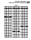
32 5 Factory Running Dimensions Tolerances, Clearances & Allowable Wear Limits For 440, 450
& 450XL VMC Compressors
VMC 11-01
SERVICE - C - REPLACES 2-01