


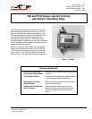
P—P28 and P128 Series Lube Oil Controls with Built-in Time Delay Relay Product/Technical Bulletin 5
*Crankcase heater cannot be c
y
cled with this hookup. See Fi
g
ure 5.
Additional controls in this line onl
y
.
P28 or P128
240V 3-phase
Operatin
g
Control
Motor
Crankcase
Heater
When Used*
L
1
L
2
L
3
T
1
T
2
T
3
240
1
2
120
L
M
A
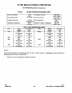
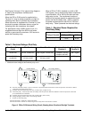
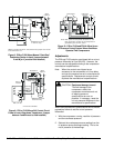
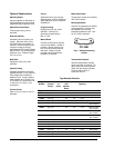
Figure 4: P28 or P128 Used on a 240V System with
240V Magnetic Starter Coil
*When crankcase heater is used, disconnect
j
umper from 2 to M
and reconnect from 2 to L.
*
Additional controls in this line onl
y
.
240V 3-phase
Operatin
g
Control
Runli
g
ht
if Used
Alarm
if Used
P28 or P128
Motor
3
2
1
240
L
M
A
120
T
1
T
2
T
3
L
1
L
2
L
3
Crankcase
Heater
When Used*
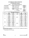
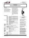
Figure 5: P28 or P128 Wired for 3-wire Control
(Jumper between 2 and M [or L] must be field
installed.)
*
*When crankcase heater is used, disconnect
j
umper from 2 to M
and reconnect from 2 to L.
P28 or P128
Additional controls
in this line onl
y
.
Alarm
if Used
Crankcase
Heater
When Used*
Ground
120 or 240V
Suppl
y
Hot
Runli
g
ht
if Used
3
1
2
L
M
A
120
240
240 or
120V
Motor
T
1
T
2
T
3
C
3
C
4
C
2
L
1
L
2
L
3
An
y
Volta
g
e
Operatin
g
Control
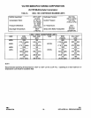
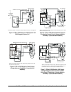
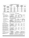
Figure 6: P28 or P128 Where Separate Supply is
Provided for Control Circuit (Jumper between
2 and M [or L] must be field installed.)
*When crankcase heater is used, disconnect
j
umper 2 to M
and reconnect 2 to L. Also, make sure that control circuit
transformer has sufficient output for additional load.
*
240V 440V
440V
3-phase
Crankcase
Heater
When Used*
Runli
g
ht
if Used
Alarm
if Used
Motor
Additional controls
in this line onl
y
.
Operatin
g
Control
P28 or P128
3
1
2
240
120
L
M
A
T
1
T
2
T
3
C
3
C
2
L
1
L
2
L
3
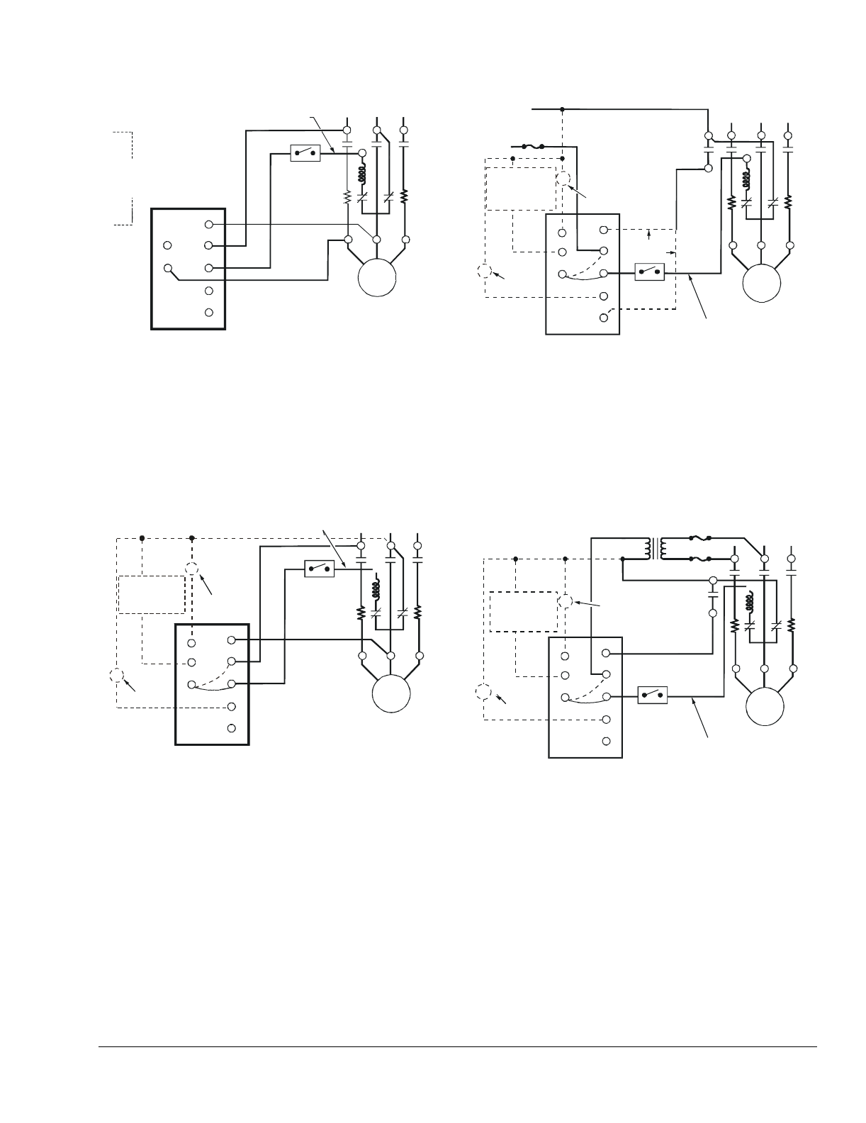
Figure 7: P28 or P128 Wired for 440V Supply
and 240V Magnetic Start Coil (Also for 550V
Using Proper Transformer) (Jumper between
2 and M [or L] must be field installed.)