VILTER MANUFACTURING CORPORATION
VILTER MultiCylinder Compressor
400 Series VMC 2/01
SERVICE - 16 - Replaces all Previous Issues
3. Unloader Piston Replacement
Before reinstalling piston, remove old ring
set. Clean and inspect for wear. Replace
piston if wear is excessive. a ring set con-
sisting of “PTFE” outer ring and a silicone
rubber inner ring is used on the piston. Re-
place ring set carefully with a new one every
time a piston is removed. With eyebolt re-
moved, place the piston into its hole in the
frame. Compress the rings with the fingers
and work them into the hole carefully so they
are not nicked or cut as the piston is moved
down. Push the piston down until it touches
the yoke lifting arm.
4. Actuator Mechanism Removal
Before a capacity control actuator mecha-
nism can be removed from the compressor,
at least one of its corresponding cylinder lin-
ers must be removed. The first step in re-
moving capacity control actuator from the
machine is to push the unloader piston down
with a block of wood. Then take a piece of
steel (
5
/
16
” in diameter) or a piece of wood,
and insert it between the two vertical rods on
the yoke assembly accommodating the short
pivot pin and fulcrum pin. This will hold the
assembly depressed and make handling
much easier. Then remove the unloader pis-
ton as detailed above. The mechanism can
then be removed through the cylinder liner
hole in the frame.
5. Actuator Mechanism Replacement
Compress the yoke assembly and place a
small piece of wood or a
5
/
16
” (7.94 mm) o.d.
steel rod between the two vertical rods men-
tioned in paragraph 4. This keeps the yoke
depressed for easier handling. Then place
the mechanism into the frame through the
cylinder liner opening and position it. Install
unloader piston as detailed above. Depress
the unloader piston with a block of wood and
remove the rod or piece of wood used to
hold the yoke assembly depressed. Then
center the mechanism between the two cyl-
inder liner holes.
VI. SAFETY VALVE (INTERNAL RELIEF)
A. Removal
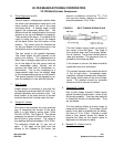
If, for any reason, the safety valve has relieved,
install a new valve. Make no attempt to adjust
the relief valve. To replace the safety valve, re-
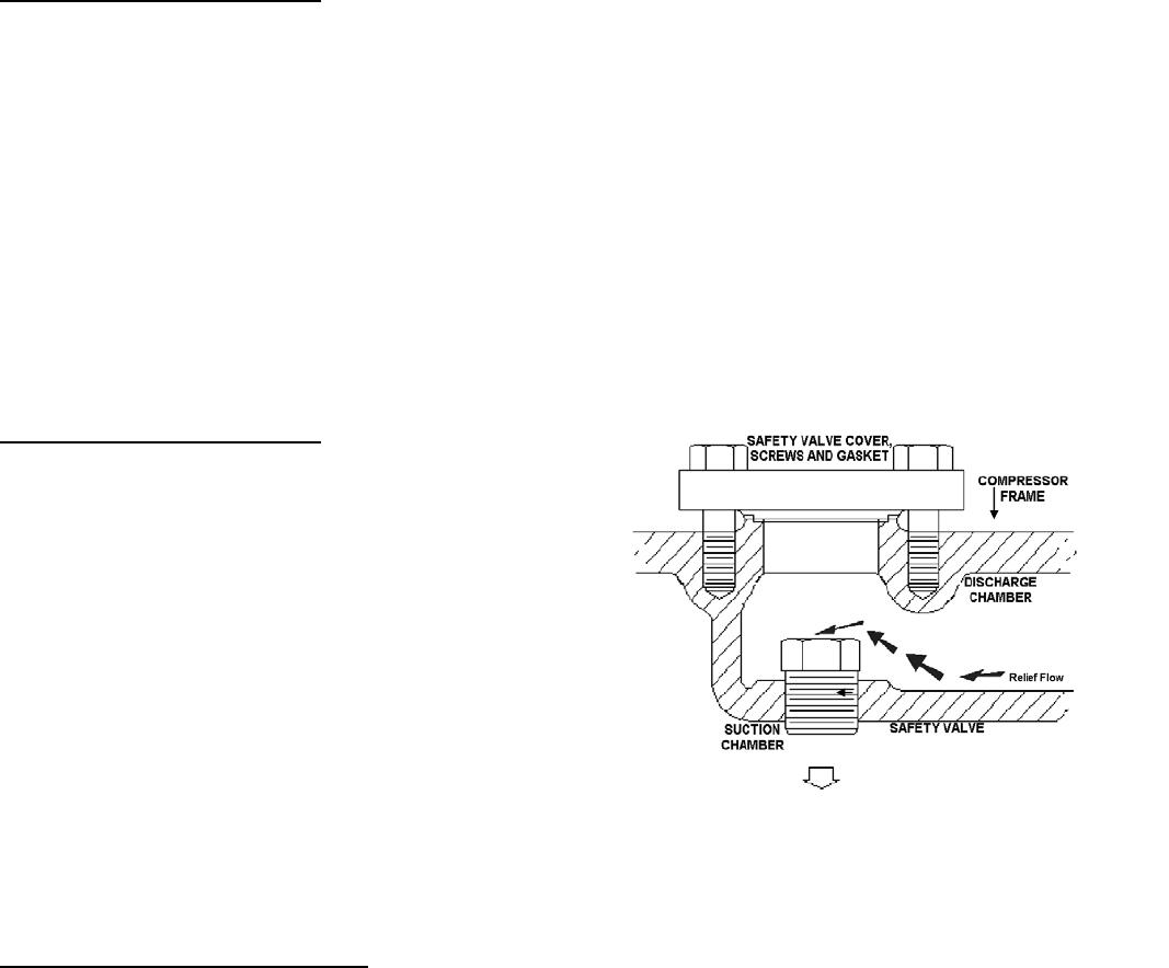
move the cover on the top of the compressor
frame marked “safety valve” by taking out the two
screws which hold it in place. Then, remove the
safety valve by using a standard 1¾” (44.45 mm)
socket.
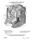
Note: Safety Valve is set at a differential pressure of 300
PSIG (2069 kPa). Maximum discharge temperature is
300°F (150°C).
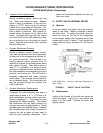
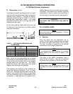
FIGURE 9. SAFETY VALVE LOCATION
B. Replacement
Lightly oil the threads of the valve and screw the
valve into place. Lightly oil a new gasket and
place it on the frame. Position the cover and
tighten it down.


