


February 2001
VILTER MANUFACTURING CORPORATION
SECTION 102-R
Replaces
PAGE 13
March 1984
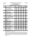
450 VMC COMPRESSORS
(High-Stage, Two-Stage, Booster and Heavy Duty)
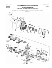
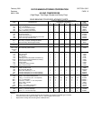
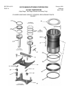
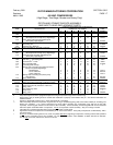
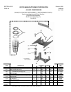
REAR BEARING COVER REPLACEMENT PARTS
QUANTITY REQUIRED PER COMPRESSOR
ITEM DESCRIPTION NUMBER OF CYLINDERS PART
2 4 6 8 12 16 NUMBER
301 thru 304 Rear Bearing Cover Assembly Kit 1 1 1 1 1 1 KT092
301 Cover, Rear Bearing 1 1 1 1 1 1 Order Kit
302 Plug, ¾” Hex Socket Head Pipe 1 1 1 1 1 1 13163E
303 Pin,
3
/
8
” x 1” Dowel (not shown) 1 1 1 1 1 1 2868H
304 Orifice, Oil Metering (not shown) 1 1 1 1 1 1 33361A
305 Gasket, Oil Pump Body 1 1 1 1 1 1 31899A
306 Oil Pump Assembly 1 1 1 1 1 1 A33480A
307 Gasket, Oil Pump Cover 1 1 1 1 1 1 31900A
308 Gasket, Oil Pump and Rear Bearing Cover Seal 1 1 1 1 1 1 33320A
309 Cover, Oil Pump and Filter Head 1 1 1 1 1 1 34565A
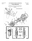
310 Filter Assy., Complete (without Bypass Relief) 1 1 1 1 1 1 A35241A
310 * Filter Assy., Complete (with Bypass Relief) 1 1 1 1 1 1 A35240A
311 Spool Assembly (without Bypass Relief) 1 1 1 1 1 1 2046A
311A,312, Spool – Strainer Tube Assembly 1 1 1 1 1 1 1448U
313 & 314
311A,312
Thru 314 & Filter Assembly (without Shell) 1 1 1 1 1 1 1448T
315A thru
319
311A * Spool Assembly (with Bypass Relief) (used on 1448C) 1 1 1 1 1 1 1448J
312 Seal, Spool End 1 1 1 1 1 1 1448H
313 Strainer Tube 1 1 1 1 1 1 1448K
314 Ring, Retaining 1 1 1 1 1 1 1448L
315 Recharge (for use with 2046A and A35241A) † 1 1 1 1 1 1 2115C
315A * Recharge (for use with A35240A and 1448J) † 1 1 1 1 1 1 1448C
316 Pressure Plate Assembly 1 1 1 1 1 1 1448M
317 Pressure Plate 1 1 1 1 1 1 1448N
318 ‘O’ Ring Seal, Pressure Plate 1 1 1 1 1 1 1448P
319 Spring, Pressure Plate 1 1 1 1 1 1 1448Q
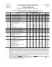
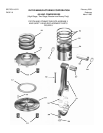
320 Plug, Steel Square Head Pipe
1
/
8
” 1 1 1 1 1 1 1190A
321 Gasket, Oil Filter Head 1 1 1 1 1 1 1448B
322 Filter Shell with Bolt Ring 1 1 1 1 1 1 A34623A
323 Screw, Hex Head Cap
7
/
16
” x 2” 4 4 4 4 4 4 1689G
324 Instruction/Nameplate (for use with A35241A) 1 1 1 1 1 1 40680AJ
324 * Instruction/Nameplate (for use with A35240A) 1 1 1 1 1 1 40680AT
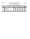
325 Gauge, 2½”, 0-300 PSI, Oil filter 1 1 1 1 1 1 2047A
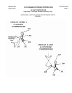
326 Elbow, ¼” 90° Female Compression 1 1 1 1 1 1 1892B
327 Tubing, ¼” O.D. Steel (“AR” = As Required) AR AR AR AR AR AR S1589A
328 ** Tee, ¼” Compression 2 2 2 2 2 2 13239C **
329 ** Connector, ¼” MPT x ¼” O.D. Compression 2 2 2 2 2 2 13229D **
330 Valve, 3-Way, Oil Filter 1 1 1 1 1 1 2030A
331 Bracket, Valve 1 1 1 1 1 1 35106A
332 Elbow, ¼” 90° Male Compression 1 1 1 1 1 1 13375D
332A ** Control, Pressure Differential 1 1 1 1 1 1 1643V **
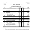
333 Gasket, Bearing Cover 1 1 1 1 1 1 31890A
334 Screw,
5
/
8
” x 2” Hex Head Cap 10 10 10 10 10 10 13152E
335 Screw, ½” x 1¾” Hex Head Cap 8 8 8 8 8 8 2796EL
NOTES:
* Filter with bypass relief is standard beginning with S/N 45497 (oil unloaded) and 60080 (gas unloaded).
** Used when center tube (Spool Assembly, Item 311) without bypass relief is used.
† Replacement recharge also includes gasket 1448B (Item 321).