


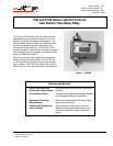
4 P—P28 and P128 Series Lube Oil Controls with Built-in Time Delay Relay Product/Technical Bulletin
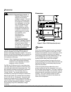
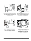
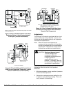
See Figures 3 through 10 for typical wiring diagrams
or refer to the compressor manufacturer’s
specifications.
When the P28 or P128 control is supplied with a
Terminal 3, it may be wired to operate a runlight for
indicating when there is sufficient net oil pressure.
When the control is supplied with a Terminal A, it can
be wired to operate a shutdown alarm or signal for
indicating when the compressor has tripped.
For applications using a 208V control circuit, it is
suggested that one leg of the 208V circuit and a
neutral or ground wire be used as a 120V source to
power the time delay relay.
When a P28 or P128 is installed on a 440 or 550
VAC system, use an external step-down transformer
to provide either 120 or 240V to the pilot and time
delay relay circuits. The transformer must be of
sufficient volt ampere capacity to operate the motor
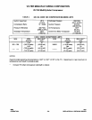
starter and the time delay relay. Table 1 presents
the power requirements for the P28 or P128 time
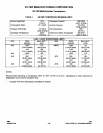
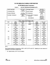
delay relay. Table 2 presents the electrical ratings.
Table 1: Electrical Power Required for
Time Delay Relay
Voltage
Timing in Seconds 12, 24, or 120V 240V
30, 45, 60, 90, or 120
15 VA 30 VA
Table 2: Electrical Ratings--Pilot Duty
Time Delay Relay
Circuit
Pilot Circuit Alarm Circuit* Crankcase Heater**
(Terminal 1)
Runlight**
(Terminal 3)
120/240 VAC 750 VA, 120/240 VAC 10W Tungsten, 120/240 VAC 10 Ampere, 120 VAC
5 Ampere, 240 VAC
10W Tungsten
24 VAC/VDC
12 VAC/VDC
125 VA, 24 VAC
57.5 VA, 24 VDC
125 VA, 24 VAC
57.5 VA, 24 VDC
-- 10W Tungsten
* Must be the same voltage as the pilot circuit.
** Must be the same voltage as the time delay relay circuit.
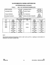
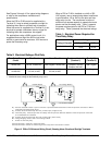
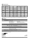
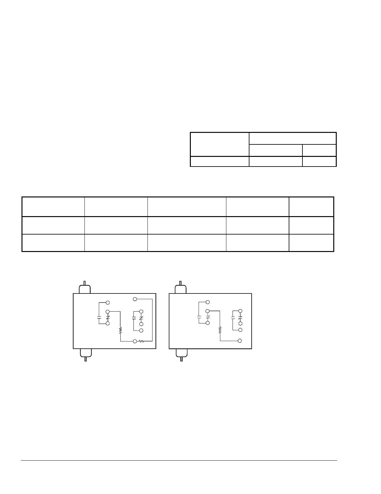
Pressure actuated contacts. Open on increase in pressure difference between oil and low pressure conntectors. Makes
and breaks time dela
y
heater circuit.
PC
1
-
Contacts close simultaneousl
y
when PC contacts open
(
runli
g
ht circuit
)
.
1
PC
2
-
Time dela
y
rela
y
. Contacts open after time dela
y
interval if pressure dfference between oil and low pressure connectors
is not established or maintained.
TD
1
-
DR
--
Volta
g
e droppin
g
resistor used in dual volta
g
e models.
H
-
Heater for time dela
y
rela
y
.
Connect Terminals L and M as a sin
g
le pole switch.
Connect Terminals 2 and 240 or 120 to ener
g
ize circuit onl
y
when motor starter is closed.
Contacts close simultaneousl
y
when TD contacts open
(
alarm circuit
)
.
1
TD
2
-
Low Volta
g
e Models
*12 volt also available.
120/240 Models
Low
Oil
3
1
2
L
M
A
24*
H
PC
2
PC
1
TD
2
TD
1
Low
Oil
3
1
2
PC
2
PC
1
L
M
A
TD
2
TD
1
DR
H
120
240
Figure 3: P28 or P128 Internal Wiring Circuit, Showing Alarm Circuit and Runlight Terminals