


VILTER MANUFACTURING CORPORATION
VILTER MultiCylinder Compressor
400 Series VMC 2/01
SERVICE - 11 - Replaces all Previous Issues
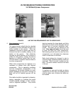
6. Drive Alignment (cont’d)
Vertical angular misalignment results when
the motor and compressor shafts are in the
same vertical plane, but not in the same
horizontal plane. A straight edge is held
against the compressor pulley face. The
distance from the straight edge to the motor
sheave at the top and bottom is compared.
They should be the same. If the back of the
motor is sitting low, the top of the sheave
will be back further than the bottom of the
sheave. The motor must be shimmed so
the top and bottom of the sheave are in the
same plane as the compressor pulley.
The last check is the parallel alignment.
This check aligns the belt grooves of the
pulley and sheave. The measurement is
taken from a straight edge held at the outer
rim to the edge of the first groove used on
the compressor pulley (usually not all
grooves are filled due to horsepower re-
quirements). This is then compared to a
measurement taken from the straight edge
to the corresponding groove on the sheave.
The sheave position is then adjusted to as-
sure the sheave is in line with the flywheel.
7. Belt Tension
Proper tension is essential to long belt life.
An improperly tensioned belt will result in in-
efficient operation and excessive heat. The
ideal tension is the least amount of tension
at which the belt will not slip under the load.
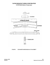
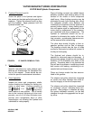
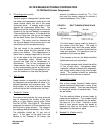
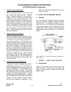
8. Single 5V, V-belts
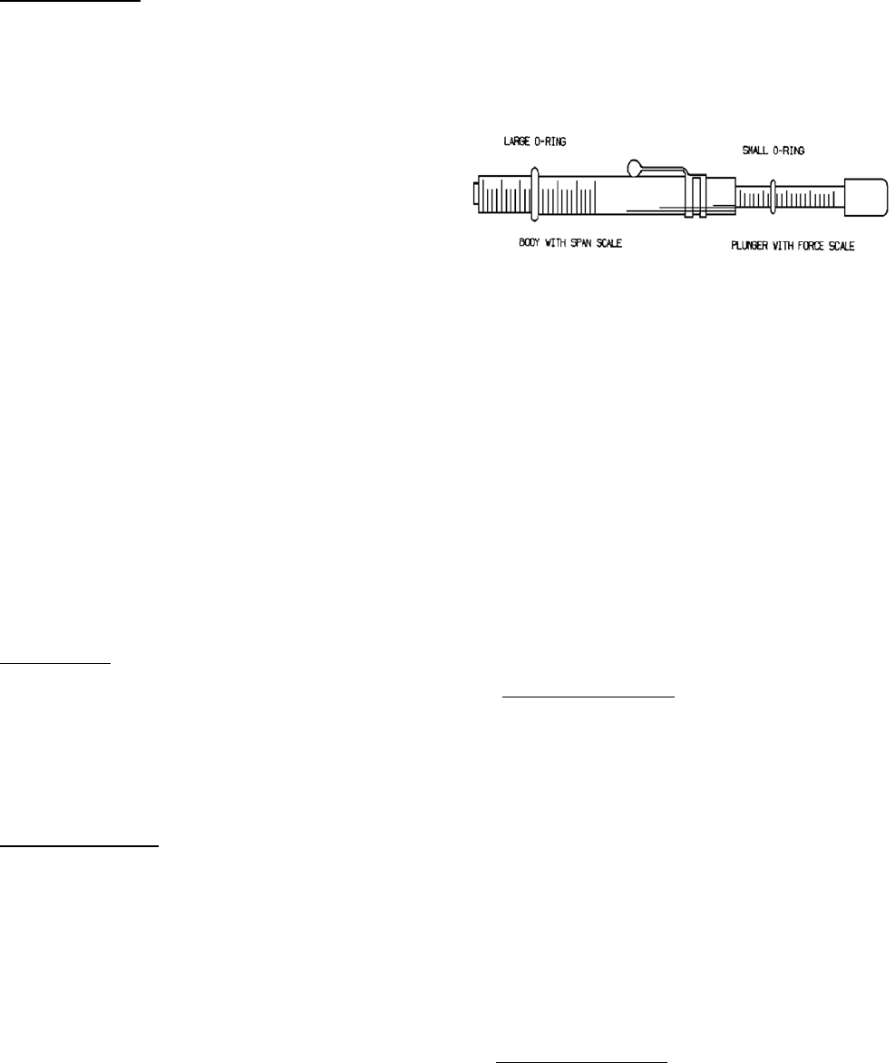
One device that provides the most accurate
way of measuring the tension of the drive
belts is a belt tension spring scale (Vilter
Part No. 3072A). See Figure 6. This device
measures the amount of force needed to de-
flect the belt a given amount. The range of
the readings should be between 12 to 18 lbs.
The deflection should be
1
/
64
” per inch of
span. If the span of the belts from the
sheave to the flywheel is 38 inches, the
amount of deflection should be
19
/
64
” (7.54
mm) and the tension required to achieve it
should be between 12 to 18 lbs.
FIGURE 6. BELT TENSION SPRING SCALE
The belt tension spring scale is placed in
the center of the belt span. The scale is
then pushed down until the proper deflec-
tion is reached. The tension should then be
read and recorded. The process is then re-
peated for the remaining belts.
If the tension is too low, the belts should be
tightened evenly and rechecked.
The tension between belts should be within
±1 lbs. of each other. Inconsistent meas-
urements indicate problems with alignment,
belt length and/or wear of the drive compo-
nents. The problem should be corrected
before the unit is returned to service.
9. Banded 5V, V-belts
Due to their design, banded V-belts require
special tensioning techniques in order to set
the tension properly. There are two methods
to check the tension of banded belts. They
are as follows:
The first method utilizes a tension tester to
measure the deflection. The number of belt
bands in the belt is multiplied by the deflec-
tion force of 12 to 18 lbs. A board or metal
plate is then placed across the bands to
equalize the force as the tension tester is
depressed on the board or plate.
9. Banded 5V, V-belts
(cont’d)