


VILTER MANUFACTURING CORPORATION
VILTER MultiCylinder Compressor
400 Series VMC 2/01
SERVICE - 21 - Replaces all Previous Issues
B. Reassembly (cont’d)
The easiest way to replace the rings on the pis-
ton is to wrap a thin piece of shim stock around
the pistons and slide the ring over this. Do not
force the rings when sliding them onto the shim
stock. The rings are brittle and may snap. A tool
is also available to aid in the installation of the
rings.
Both compression and oil rings are marked to
indicate the top of the ring. Install the compres-
sion rings with the identifying mark to the top of
the pistons. Rotate the end gaps on each ring so
they are not aligned on the piston.
Remove the piston assembly. Check the fit of
the piston pin bushing for wear. The 440 and
450 have a different pin and piston design from
the 450XL compressor. The 440 and 450 piston
and piston pin bushing have a “slip” fit. When
replacing the piston and bushing, the bushing
must be reamed to the correct “slip” fit after in-
stallation into the rod to accommodate the new
piston pin. The 450XL piston and piston pin
bushing cannot be changed in the field due to
tolerances. They must be purchased as a unit
with the connecting rod and piston assembly.
The piston pin should not slip easily into its hole,
but it must not be driven down. It may be neces-
sary, however, to tap the pin lightly with a block
of wood and a hammer. Be sure the hole in the
rod pin bushing is aligned so the pin can slip
through it. When the pin has been tapped in far
enough, install the two piston pin lock rings, one
at each end of the piston pin.
Two styles of bearing half inserts have been
used in the compressor. One style has only the
hole in the rod half to allow oil to travel up the
rod. The second type has annular grooves to
allow a continuous supply of oil.
CAUTION
The bearing inserts should never be spread
open, by hand or any other means, to provide
for a tighter fit in the rod.
If an inspection indicates the rod bearing sur-
faces are worn, replace the bearing insert. As-
semble bearing inserts by pressing them into
place, making sure the notch in the rod is clear.
If the bearing insert does not properly fit in the
rod and it falls out during assembly, either the
bearing insert or the rod is worn or incorrectly
made.
When installing the bearing insert into the con-
necting rod, make sure there is no oil on the con-
necting rod or the back side of the bearing insert.
If the original bearings have failed, check the
crankshaft bearing surface. If there are slight
imperfections due to bearing failure, remove by
polishing with fine crocus cloth. Then, clean the
bearing surface with suitable refrigeration cleaner
and lubricate with clean compressor oil.
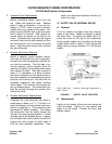
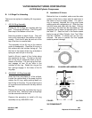
Lubricate the inside of the cylinder and the entire
piston. The recommended method of installing
the piston in the liner is with the use of a Piston
Ring Compressor. See Figure 10.
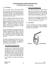
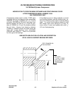
Attach the oil line to the bottom of the front hous-
ing. Do not over tighten the nut. Rotate the shaft
a few times to help the seal settle into position.
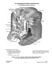
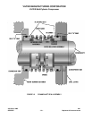
FIGURE 11. FRONT COVER ASSEMBLY AND
DISASSEMBLY STUD