


VILTER MANUFACTURING CORPORATION
VILTER MultiCylinder Compressor
400 Series VMC 2/01
SERVICE - 3 - Replaces all Previous Issues
A. Disassembly (cont’d)
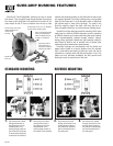
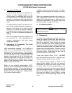
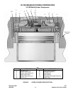
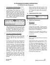
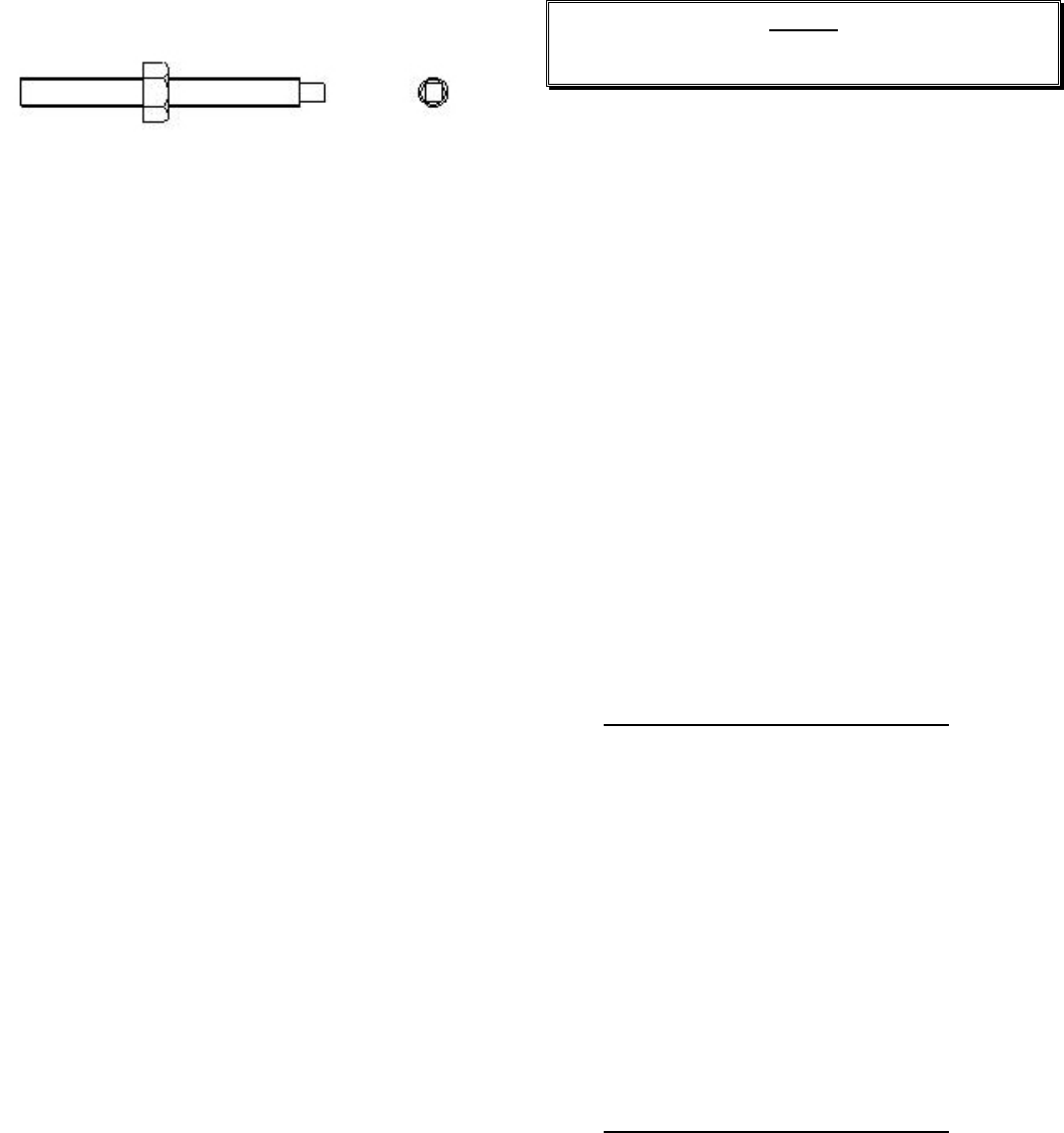
FIGURE 1. BEARING AND CYLINDER
COVERS ASSEMBLY & DISASSEMBLY STUD
B. Assembly
Before replacing the cover on the compressor,
inspect the gasket surfaces of the cover and
compressor frame. Remove any debris adhering
to either of these surfaces. Remove any burrs or
rough edges from the mating surfaces to ensure
a tight seal. Replace studs, if removed. Lightly
lubricate both sides of the head gasket. Position
the gasket over the studs and against the com-
pressor frame in the correct orientation. Place
the springs on top of the safety head yokes (ro-
tating the spring until it stays on the yoke). Place
the cover down over the studs and slowly lower
on top of springs. When all pieces are in align-
ment, place the nuts on the studs and start to
tighten. When the cover is secure within 1¼”
(31.75 mm) of the gasket, install the rest of the
screws so they come in contact with the cover.
This will ensure they will not cross thread in the
holes.
Do not tighten each screw separately, however.
Alternate on opposing screws, until the cover is
seated on the gasket. Remove the studs and
replace with screws. Finish tightening the screws
in an opposing pattern to the recommended
torque values shown in Table 2, 3 or 4 (depend-
ing upon your compressor model). Reinstall the
capacity control and head cooling lines, and
check for leaks.
III. SUCTION AND DISCHARGE VALVE PLATES
NOTE:
Before proceeding, refer to Paragraph I, “General
Service Instructions”.
A. Disassembly
To service valve plates in the compressor, re-
move the cylinder covers (refer to paragraph
II.A). In cylinders without unloaders, the valve
assemblies may be removed as soon as the cov-
ers are removed.
On compressor cylinders equipped with unload-
ers, the unloader needs to be forced down before
the valves are serviced. If the unloader remains
up, the suction valve is forced off its seat, and will
not seat and locate properly during reassembly.
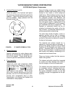
To hold the unloader mechanism down, remove
the plug from the hole ‘B’ in the frame. Force the
unloader piston down and insert a short
5
/
16
”
(7.93 mm) diameter metal rod through the hole to
restrain the piston. Use a wooden block to force
the piston down to avoid scratching or damaging
the top of the unloader piston. Once the piston is
held down, the valve assemblies can be ser-
viced.
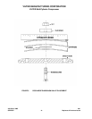
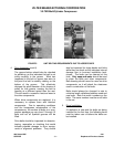
1. 440 Compressor (Mushroom Style)
(See Figure 7)
Lift out the safety head yoke, which holds
the safety head assembly in place. When
the yoke is out, lift out the safety head as-
sembly and suction valve plate.
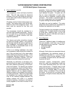
To disassemble the safety head assembly,
remove the locknut on the valve retaining
screw.
1. 440 Compressor (Mushroom Style)
(cont’d)