


VILTER MANUFACTURING CORPORATION
VILTER MultiCylinder Compressor
400 Series VMC 2/01
SERVICE - 19 - Replaces all Previous Issues
heater wiring and heater cover, add oil to crank-
case and turn on power to the heater to preheat
the oil for operation of compressor.
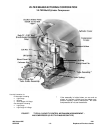
XI. CRANKSHAFT SEAL
NOTE:
Before proceeding, refer to Paragraph I, “General
Service Instructions”.
A. Oil Seal Leakage
In refrigeration compressors, a slight amount of
oil leakage past the crankshaft seal is normal and
desirable. A few drops per minute is reasonable.
This leakage performs two important functions. It
helps lubricate the neoprene bellows and o-rings,
and it helps cool mating rotating parts to provide
less wear and longer life. A receptacle for collec-
tion is recommended.
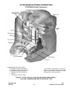
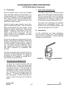
B. Removal
The flywheel or coupling will have to be removed.
Detach the tubing line on the bottom of the front
housing. Oil will drain from the seal chamber, be
prepared to collect it. After the oil has drained,
remove the 8 screws holding the cover. When
removing the cover, caution should be taken be-
cause the front carbon seal might come off with
the cover. At this time, if the seal is going to be
reused, clean the surface of the shaft and avoid
getting anything in the housing area.
Grab the front rubber bellows and pull forward. It
should release. If not, pry by the tabs on the
metal ring (alternating force from side to side) to
remove it. Remove the large spring.
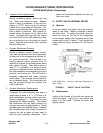
Next step is to remove the 3 screws in the re-
tainer that hold the inner mirror seat. Put 2 of
these screws in the tapped holes of the retainer.
Rotate the retainer so screws are at 3 and 9
o’clock positions. Pull on the screws to aid in
removing the retainer and the rest of the seal as-
sembly. Clean out the seal chamber with suit-
able refrigeration parts cleaner. Afterwards, coat
the area and crankshaft to keep them from rust-
ing.
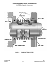
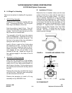
C. Installing A New Shaft Seal
Remove the mirror seats from the inner retainer
and outer cover. The mirror face can be re-
moved by tapping on back side that is exposed in
each part. Make sure these parts are then
cleaned. Place either on a flat surface with the
recess up. Oil the o-ring sealing area. Take the
mirror face (do not touch the mirrored surface),
oil outer o-ring and lay it in the cover or retainer
with the mirror face upward. Using a very clean
cloth or similar item, cover mirror face and, using
palm of hand, set it in the recess. Repeat this
assembly process for the other mirror face.
Vilter recommends that if any part of a seal
needs replacement, the entire shaft seal should
be replaced with a new one.
Make sure the oil passage in the shaft is unob-
structed. Install the inner retainer with mirror
face, flush in front housing, with the word “TOP”
at the top. Tighten down evenly with the 3
screws.
The shaft seal assembly is symmetrical. It can
be installed in either direction. Spray oil on inner
mirror face. Liberally coat oil on one of the bel-
lows and carbon assemblies. Avoid coming in
contact with carbon. Carefully slip the assembly
on the shaft until the carbon touches the mirror
face. Put the spring over the shaft and seal on
the bellows assembly, and slide it onto the shaft
to join up with the spring. With the new cover
gasket in place, install the cover over the end of
the shaft.
Push the cover all the way on, lining up the bolt
holes so the drain is to the bottom. Tighten down
the 8 screws evenly to the torque requirements in
Table 2, 3 or 4 (depending upon compressor
model).
XII. CONNECTING RODS AND PISTONS
NOTE:
Before proceeding, refer to Paragraph I, “General
Service Instructions”.