


February 2001
VILTER MANUFACTURING CORPORATION
SECTION 102-R
Replaces
PAGE 17
March 1985
450 VMC COMPRESSORS
(High-Stage, Two-Stage, Booster and Heavy Duty)
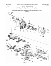
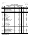
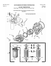
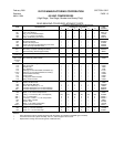
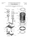
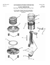
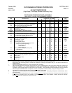
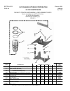
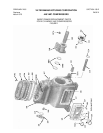
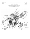
PISTON AND CONNECTING ROD ASSEMBLY
AND SAFETY HEAD REPLACEMENT PARTS
QUANTITY REQUIRED PER COMPRESSOR
ITEM DESCRIPTION NUMBER OF CYLINDERS PART
2 4 6 8 12 16 NUMBER
501 Thru Piston, Rings and Pin Assembly Kit 2 4 6 8 12 16 KT213
506
501 Piston, Rings and Connecting Rod Assy Kit
Thru (All Compressors except 16 Cyl. High-Stage) 2 4 6 8 12 16 KT478
512 Piston, Rings and Connecting Rod Assy Kit
(Heavy Duty High-Stage #) - - - - - - 8 - - 16 KT478A
501 Piston Ring, Compression 6 12 18 24 36 48 31989M
502 Piston Ring, Oil 2 4 6 8 12 16 31989N
504 Retaining Ring, Wrist Pin 4 8 12 16 24 32 33244A
505 and Piston and Wrist Pin Assembly (matched) 2 4 6 8 12 16 ***
506
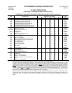
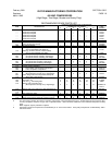
507 Connecting Rod Assembly with Bearings Kit
Thru (All Compressors except 16 Cyl. High-Stage) 2 4 6 8 12 16 KT463
512 Connecting Rod Assembly with Bearings Kit
(Heavy Duty High-Stage #) - - - - - - 9 - - 16 KT463A
507 Bushing, Wrist Pin 2 4 6 8 12 16 31896B *
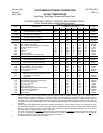
508 Lock Nut,
3
/
8
”, Connecting Rod 4 8 12 16 24 32 2028A
509 Nut, Plain Hex
3
/
8
”-UNF 4 8 12 16 24 32 2027A
510 Bolt, Connecting Rod 4 8 12 16 24 32 31955A
511 Connecting Rod and Cap 2 4 6 8 12 16 **
+512 Bearing Half, Connecting Rod (All Compressors -
Except 16 Cylinder High-Stage)
Standard Size 2 4 6 8 12 16 KT512
0.015” Undersize 2 4 6 8 12 16 KT513A
0.030” Undersize 2 4 6 8 12 16 KT513
512 Bearing Half, Connecting Rod (Heavy Duty
High-Stage #) - - - - - - 8 - - 32 35273ST
513 Spring, Safety Head 2 4 6 8 12 16 35252A
514 Safety Head and Pins Assembly (Standard Comp) 2 4 6 8 12 16 A35082A
and 518 Safety Head and Pins Assembly (Hi Suction Comp #) 2 4 6 8 12 16 A35272A
514 Pin, Roll, 0.187” dia. x
11
/
16
” lg. † 8 16 24 32 48 64 1712F
515 Safety Head Yoke Kit (includes 4 of item 514) 2 4 6 8 12 16 KT543
516 Spring, Valve 16 32 48 64 96 128 33803A
517 Plate, Discharge Valve 2 4 6 8 12 16 35080SS
518 Safety Head 2 4 6 8 12 16 **
519 Spring, Valve 8 16 24 32 48 64 33803A
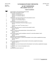
NOTES:
A. Early 450 compressors were equipped with pistons having 2 compression rings and 2 oil control rings.
* Replacement wrist pin bushing must be reamed after installation to properly accommodate wrist pin. See Service Instructions for
additional details.
** Shown for disassembly purposes only. Order appropriate Kit or Assembly.
*** Piston Assembly with three compression rings and one oil ring is standard beginning with serial number 45664 (oil unloading) and
60433 (gas unloading). It is a direct replacement for former piston assembly (two compression rings and two oil rings with
expander). Piston ring part numbers are the same for either assembly. Current assembly is interchangeable with and can be mixed
with former piston assemblies within a compressor. Do not
use expanders in either assembly – they are no longer needed.
† Install with pin’s outside longitudinal seam facing outside diameter of safety head.
# High Suction Pressure Compressors are identified by an ‘X’ in the serial number. Heavy Duty Compressors are identified by ‘HD’ in
the serial number.
+ Do not
use undersize bearing halves on 6, 8 and 12 Cylinder Belt Driven High-Stage compressors. Bearing half sets with quantities
enough for one connecting rod are also available. For sets without Lock Nuts, order 35086ST, 41726ST, 35214ST or 35273ST.
For sets with
Lock Nuts, order KT512, KT513 or KT513A.