


February 2001
VILTER MANUFACTURING CORPORATION
SECTION 100-R
Replaces
PAGE 5
May 1985
450XL
®
* VMC COMPRESSORS
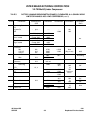
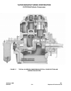
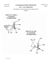
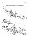
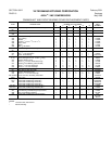
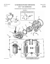
BASIC FRAME REPLACEMENT PARTS
QUANTITY REQUIRED PER COMPRESSOR
ITEM DESCRIPTION NUMBER OF CYLINDERS PART
2 4 6 8 12 16 NUMBER
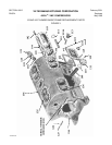
101 Frame 1 1 1 1 1 1 +
102 Screw,
5
/
8
” x 3½” Hex Head Cap
(Used with Water Jacket) 20 40 60 80 120 160 13152L
102 Screw,
5
/
8
” x 2½” Hex Head Cap
(Used when Water Jacket not used) 20 40 60 80 120 160 13152G
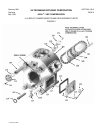
103 Cover, Water Jacket (Ammonia and R22) 1 2 3 4 6 8 30299A
104 Gasket, Water Jacket (Ammonia and R22) 1 2 3 4 6 8 33329A
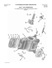
105 Cover, Cylinder
Banks w/o Capacity Reduction - - 1 - - 2 - - 4 A30332A
Banks w/Capacity Reduction (Oil Act.) - - 1** - - 2** - - 4** 30332B
Banks w/Capacity Reduction (Gas Act.) - - 1 - - 2 - - 4 30332G
Banks w/o Capacity Reduction 1 - - 1 - - 2 - - A30364A
Banks w/Capacity Reduction (Oil Act.) 1** - - 2** - - 4** - - 30364B
Banks w/Capacity Reduction (Gas Act.) 1** - - 2** - - 4 - - 30364G
Banks w/o Capacity Reduction (Two-Stage) - - - - 3 - - 6 - - A30364A
106 Gasket, Cylinder Cover 1 2 3 4 6 8 33330A
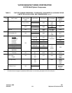
107 Stud,
5
/
8
” x 3” (shown only on 2 cylinder) 8 4 4 4 8 8 13156D
107 Stud, ¾” x 3¼” (not shown) - - 4 4 4 - - - - 13157D
107A Nut, 5/8-11NC-2B 1726G
107A Nut, ¾-10NC-2B - - 4 4 4 - - - - 1726H
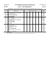
108 Tee, Suction (++)
2½” x 2½” 1 - - - - - - - - - - A30319A
3½” x 3” - - 1 - - - - - - - - A32417B
Elbow, Discharge (++)
2” x 2” (Ammonia) 1 - - - - - - - - - - 12270E
2½” x 2½” (Ammonia) - - 1 - - - - - - - - 12270F
3” x 3” (Ammonia) - - - - 1 - - 2 2 12271E
4” x 3” (Ammonia) - - - - - - 1 - - - - A32498A
109 Suction Screen - - 1 - - - - - - - - A32428A
109 Suction Screen - - - - - - 1 - - - - A32428D
109 Suction Screen - - - - - - - - 2 2 A32565A
109-A Bag, Suction Screen (not shown) - - 1 - - - - - - - - A33474A
109-A Bag, Suction Screen (not shown) 1 - - 2 3 - - - - A33474B
109-A Bag, Suction Screen (not shown) - - - - - - - - 2 2 A33474G
110 Gasket, Suction Screen Cover 1 - - 2 2 - - - - 31892A
110 Gasket, Suction Screen Cover - - - - - - - - 2 2 33493A
110 Gasket, Suction Cover - - 1 - - 1 - - - - 11323J
111 Cover, Suction Screen 1 - - 2 2 - - - - 31893A
111 Cover, Suction Screen - - - - - - - - 2 2 33492A
111 Cover, Suction Screen - - 1 - - 1 - - - - 13706A
112 Screw,
5
/
8
” x 2” Hex Head Cap - - 5 - - 5 - - - - 13152E
112 Screw, ½” x ½” Hex Head Cap 6 - - 12 12 16 16 2796E
113 Valve, ½” Oil Charge and Drain (Ammonia) 1 1 1 1 1 1 1956B
113 Valve, ½” Oil Charge and Drain (Halocarbon) 1 1 1 1 1 1 1956A
113-A Nipple, ½” x 4” Sch. 80 Pipe 1 1 1 1 1 1 13189G
114 Gasket, Crankcase Oil Screen 1 1 1 1 1 1 31889A
115 Crankcase Oil Screen Assembly 1 1 1 1 1 1 A31886A
116 ++ Plug, ¾” Hex Head Pipe (not shown on 12 & 16) 1 1 1 1 1 1 13264E
116 ++ Plug, ½” Hex Head Pipe (not shown on 2 thru 8) 1 1 1 1 1 1 13264D
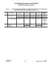
NOTES:
A. Unless otherwise indicated, quantities shown are for compressors with standard capacity reduction, and may vary if compressor is
equipped with other versions. See Page 13 for application notes.
* Patents Pending.
** Items shown are for compressors with optional oil unloading or optional single cylinder unloading. See Page 15 for application notes.
+ Part Number on application.
++ May not be shown, or only shown typically on one illustration.