


VILTER MANUFACTURING CORPORATION
VILTER MultiCylinder Compressor
400 Series VMC 2/01
SERVICE - 17 - Replaces all Previous Issues
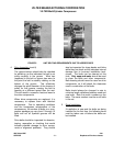
VII. OIL PRESSURE ADJUSTMENT ASSEMBLY
A. Disassembly
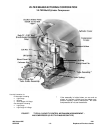
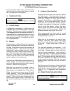
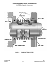
The oil pressure adjustment assembly is located
in the front bearing housing. It consists of a
spring loaded ball positioned in a machined seat
in the top of the front bearing housing. An adjust-
ing screw turned in and out changes the amount
of oil bypass, thus changing the oil pressure.
Remove the cap. A packing tool is required to
remove the gland nut (Vilter Part No. A33781A).
After the gland nut has been removed, use a
large screwdriver to turn the stem counterclock-
wise and remove it completely. The packing with
2 washers should also come out. Using a pencil
magnet, pull out the spring and steel ball.
B. Reassembly
Clean the steel ball and place in the hole. Place
the stainless steel spring on top of it. Screw the
adjustment stem in the hole to get threads
started. Place a washer over the end, then pack-
ing, then the other washer. The adjustment stem
may have to be turned in so the packing nut can
be installed and tightened. Adjustments of the oil
pressure will have to be reset after start up. Re-
place the cap and gasket afterwards.
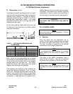
C. Adjustment
To provide quick response of the compressor
unloader mechanism, it is recommended the oil
pressure relief valve be set to maintain 40 psi
(275.79 kPa) net oil pressure. Net oil pressure
should be held at 35 psi (241.32 kPa) and 40 psi
(275.79 kPa). Net oil pressure is calculated by
subtracting the compressor suction pressure
from the oil pressure gauge reading while the
compressor is running.
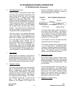
VIII. TRI-MICRO OIL FILTER
NOTE:
Before proceeding, refer to Paragraph I, “General
Service Instructions”.
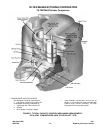
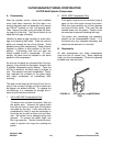
A. Removal
To remove the oil filter, drain the tank by remov-
ing the pipe plug on the bottom or side. Next re-
move one of the front screws. It can then be
threaded back in at least 2 turns, or a ¼” (6.35
mm) longer screw can be used and also
threaded in 2 turns. This will be the pivot point or
hinge to swing the filter and tank out for ease of
removal. By unscrewing the remaining 3 screws
alternately, the tank will start to lower until the
first screw installed comes in contact with the fil-
ter adapter. Force the center tube top plate
down and out of its connection hole while pivot-
ing the filter tank. Now that the filter and center
tube can be removed, disassemble the center
tube by removing the bottom spring plate. Slide
the old filter off and discard properly. The tube
should be washed off and clean.
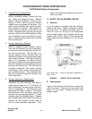
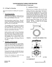
B. Replacement
Make sure to remove the used gasket of the filter
adapter and install a new one. After cleaning the
tank, reinstall the pipe plug in the drain. Install it
on its pivot screw. Add fresh oil to fill half the
tank. Reassemble the new filter on the center
tube. Slowly place the filter in the tank and allow
the filter to absorb the new oil. Pivot the tank un-
der the adapter and align the center tube in its
hole. Start the remaining 3 screws than tighten
the tank flange to the adapter. The proper
placement of the mechanism, once in the frame,
is having the curved sides of the bottom plate on
the mechanism aligned between the lower liner
bores.