


SECTION 105-R
VILTER MANUFACTURING CORPORATION
February 2001
PAGE 11
Replaces
440 VMC COMPRESSORS
August 1982
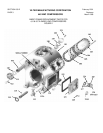
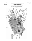
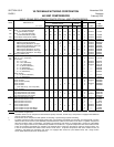
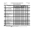
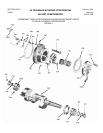
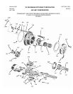
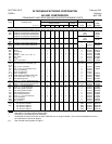
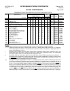
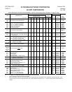
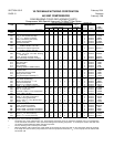
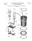
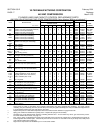
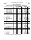
CRANKSHAFT AND FRONT BEARING COVER REPLACEMENT PARTS
NO. REQ. PER COMPRESSOR SERIAL NO.
ITEM DESCRIPTION
SINGLE STAGE
TWO-
STAGE
PART
NO. OF CYL.
2 4 6 8 12 16 6 12 FROM THRU NUMBER
231 Retainer, Rear Bearing † 1 1 1 1 1 1 1 1 0 Present 31904A
231A Rear Bearing and Lock Pin Kit 1 1 1 1 1 1 1 1 0 Present KT353
231B
231A Pin, Bearing Lock + 1 1 1 1 1 1 1 1 4233 Present 33678A
231B Bearing, Rear Crankshaft 1 1 1 1 1 1 1 1 0 Present A33509A
232 Screw,
5
/
16
” x 1” Hex. Socket Head Cap 4 4 4 4 4 4 4 4 See 13160D
232 Screw,
5
/
16
” x 1½” Hex. Head Cap. 4 4 4 4 4 4 4 4 Note † 1736G
233 Crank, Oil Pump Drive 1 1 1 1 1 1 1 1 0 Present 33403A
234 Cap, Bearing Support * - - - - - - - - 1 1 - - 1 0 Present *
235 Pin, ¼” x 1” Dowel * - - - - - - - - 2 2 - - 2 0 Present 13162X
236 Bolt, ½” x 1¾” Machine - - - - - - - - 4 4 - - 4 0 Present 11396D
237 Bearing Half, Upper Right or Lower Left - - - - - - - - 2 2 - - 2 0 Present 33508A
238 Bearing Half, Upper Left or Lower Right - - - - - - - - 2 2 - - 2 0 Present 33508B
239 Oil Dam, Center Bearing †† - - - - - - - - 2 2 - - 2 0 Present 33498A
240 Pin, Threaded Taper - - - - - - - - 1 1 - - 1 0 Present 33497A
241 Case, Bearing Support * - - - - - - - - 1 1 - - 1 0 Present *
242 Washer, ½” Spring Lock - - - - - - - - 4 4 - - 4 0 Present 13165F
243 Nut, ½” Hex - - - - - - - - 4 4 - - 4 0 Present 1726E
244 Nut,
9
/
16
” Hex - - - - - - - - 1 1 - - 1 0 Present 13253F
245 Screw, ¼” x ½” Hex. Head Cap †† - - - - - - - - 8 8 - - 8 0 Present 2796AC
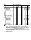
246 Key, Crankshaft 1 1 1 1 - - - - 1 - - 0 Present 31994B
246 Key, Crankshaft - - - - - - - - 1 1 - - 1 0 Present 33505B
247 Screw, Flywheel Hub 1 1 1 1 1 1 1 1 0 Present 31956A
248 Washer, Fllywheel Hub Screw - - - - - - - - 1 1 - - 1 0 Present 33495A
NOTES:
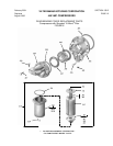
* Matched set with pin, sold as assembly A32163A. Shown in three parts to illustrate disassembly.
+ A bearing lock pin (Item 231A) is used to keep outer face of bearing (Item 231B) from turning. If compressor
does not have groove in bottom of rear bearing cover (Item 301), make a notch with a ¼” deep radius and 1
7
/
8
”
long to accommodate pin in cover.
† Mounting holes on retainer (Item 231) were changed from counterbored holes to plain, straight-thru holes. Use
replacement screw, part number 13160D, on the former retainer with counterbored holes. Use replacement
screw, part number 1736G, on current retainer with straight-thru holes.
†† Dams (Item 239) and screws (Item 245) are not needed when using VILTER’s patented joined crankshafts. In
this design version (introduced in 1980) two 6 cylinder or two 8 cylinder crankshafts are joined by a sleeve to form
an inseparable
12 cylinder or 16 cylinder crankshaft. This specially machined sleeve eliminates the dams. This
design is completely interchangeable with the former design.
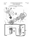
††† See page 9 for symbol regarding this information. Compressors below serial number 21355 were furnished with
the no longer available front bearing cover assemblies A30294A (2,4,6, and 8 cylinders) or A32162A (12 and 16
cylinders), and front bearing retainer 31885A (2,4,6, and 8 cylinders) or 33500A (12 and 16 cylinders) without
the
oil hole. Former front bearing retainers (31885A or 33500A) without
oil holes cannot be used with current front
bearing cover assemblies A36240A (2,4,6, and 8 cylinders) and A36241A (12 and 16 cylinders), as there is no
way for oil to get to the bearing. If front bearing cover is being replaced, a current front bearing retainer (31885A
or 33500A with
oil hole) must be ordered also, unless one of these current styles is already being used. If a
current front bearing retainer, (31885A or 33500A, both with
oil hole) is used with former style cover (A30294A or
A32162A) having an oil hole, remove orifice in cover (A30294A or A32162A) and replace with solid
1
/
8
” pipe plug.