


VILTER MANUFACTURING CORPORATION
VILTER MultiCylinder Compressor
400 Series VMC 2/01
SERVICE - 14 - Replaces all Previous Issues
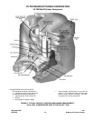
2. Actuator Mechanism Removal
The first step of removing capacity control
actuator from the machine is to push the
unloader piston down with a block of wood.
This holds the assembly depressed and
makes handling much easier.
Push the assembly away from the unloader
piston until the notch in the yoke lifting arm
slides free of the flats on the long pivot pin.
Then, remove the mechanism through the
liner hole in the top of the frame. Remove
the long pivot pin from the shaft of the pis-
ton. Now slide the piston out of the cylinder
and slip the ring or rings off the piston, taking
care not to break any.
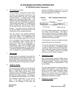
NOTE:
Gas actuated unloader pistons have two grooves
and use four metal piston pins. Oil actuated
unloader pistons have one groove and use a
rubber piston ring (o-ring).
3. Actuator Mechanism Replacement
Gas actuated unloader piston:
Clean the piston thoroughly and place four
steel rings in each groove. Work the rings in
carefully. Avoid breaking them. Place the
piston in the cylinder and compress the rings
to work them into the cylinder.
Oil actuated unloader piston:
Clean the piston thoroughly and place the o-
ring on it. Work the o-ring on carefully to
avoid breaking or excessively stretching it.
Liberally coat piston and o-ring, as well as
cylinder bore, with compressor oil. Place the
piston in the cylinder and compress the o-
ring to work it into the cylinder.
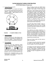
Next, insert the long pivot pin into its hole in
the piston shaft and position it so the flats
will receive the slot of the yoke lifting arm.
The end of the pin is machined flat so the in-
staller can see the position of the inner flat.
Compress the yoke assembly and place a
piece of
5
/
16
” (23.81 mm) o.d. steel rod under
the rear of the lifting rod. This keeps the
yoke depressed for easier handling. Place
the yoke into the frame through the cylinder
opening and position it so the slot on the
yoke lifting arm registers with the flats on the
long pivot pin. Depress the piston with a
block of wood, and remove the rod or piece
of wood used to hold the yoke assembly de-
pressed. Then, center the assembly be-
tween the two cylinder liner holes.
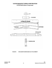
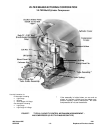
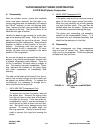
B. New Style (Bullet Type)
1. Lift Pins, Ring and Springs Removal
In order to put the unloading mechanism
back in the cylinder liner, place the lift pins
with the springs around them in their holes.
Place the lift ring on the pins with the smaller
inside diameter facing top of the liner so it
will slip over and cover the retainer when it is
in place. Placing the liner on its side and
holding the lift ring back against the pins and
springs, slide the ring retainer over the liner
into its groove.
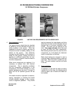
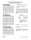
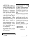
2. Unloader Piston Removal
It is not necessary to remove or disturb the
actuator mechanism or the cylinder liners to
remove the unloader piston. There are two
holes in the top of the unloader piston. One
is threaded, the other is not. Use ¼”-20NC
eyebolt in the center hole. Use the other
hole to keep the piston from turning in the
hole in the frame while doing this. Using the
eyebolt as a handle, pull the piston out of its
hole in the frame.